Cooling storage and method of operating the same

a technology of cooling storage and storage chamber, which is applied in the direction of domestic cooling apparatus, static/dynamic balance measurement, instruments, etc., can solve the problems of food in the other storage room to be cooled later that cannot be cooled early, the temperature inside the room to rise above the on temperature even temporarily, and the temperature rise within the freezing room cannot be sufficiently suppressed

Inactive Publication Date: 2012-07-03
HOSHIZAKI ELECTRIC CO LTD
View PDF26 Cites 23 Cited by
  • Summary
  • Abstract
  • Description
  • Claims
  • Application Information

AI Technical Summary

Benefits of technology

[0041]According to the present invention, the ratio of the refrigerant supply time to each of the first and second evaporators is controlled based not on a deviation between a target temperature set for each of the first and the second storage rooms and an actual storage room temperature measured in each storage room, but on the integrated value obtained by integrating the difference of these deviations. Accordingly, even when, for example, the door is temporarily opened and the external air flows into the storage room, causing the storage room temperature to be temporarily rise, the one-storage room cooling mode can be prevented from unnecessarily shifting to the alternate cooling mode since no rapid change appears in the integrated value of temperature deviations. Moreover, the alternate cooling mode can be repeated at a short cycle, and thereby providing a cooling storage and an operating method thereof capable of executing the pull-down operation at a predetermined temperature curve.

Problems solved by technology

However, in the above configuration, when a food of high temperature is stored in both the storage rooms, there occurs a problem that the food in the storage room to be cooled on ahead would have no trouble, whereas the food in the other storage room to be cooled later would not be able to be cooled early enough.
However, even with the above configuration, the cooling is immediately switched to the alternate cooling mode, when, for example, the cooling mode was switched to the freezing room cooling mode since a food of high temperature was stored in the freezing room and caused the temperature inside the room to rise above the ON temperature, and after that, this time, the door of the refrigeration room is opened and closed frequently, causing the temperature inside the room to rise above the ON temperature even temporarily.
This delays the cooling of the freezing room since apart of the cooling performance is spared for cooling the refrigeration room, and eventually, the temperature rise within the freezing room cannot be sufficiently suppressed.
But then again, if the switching in the alternate cooling mode is conducted at a short cycle such as, for example, 3:2 minutes, the problem of sparing the cooling performance for the refrigeration room becomes unfavorably prominent even when a quick cooling of the freezing room as mentioned above is required.

Method used


Image

  • Cooling storage and method of operating the same
  • Cooling storage and method of operating the same
  • Cooling storage and method of operating the same

Examples


embodiment 1

[0057][Embodiment 1 ]

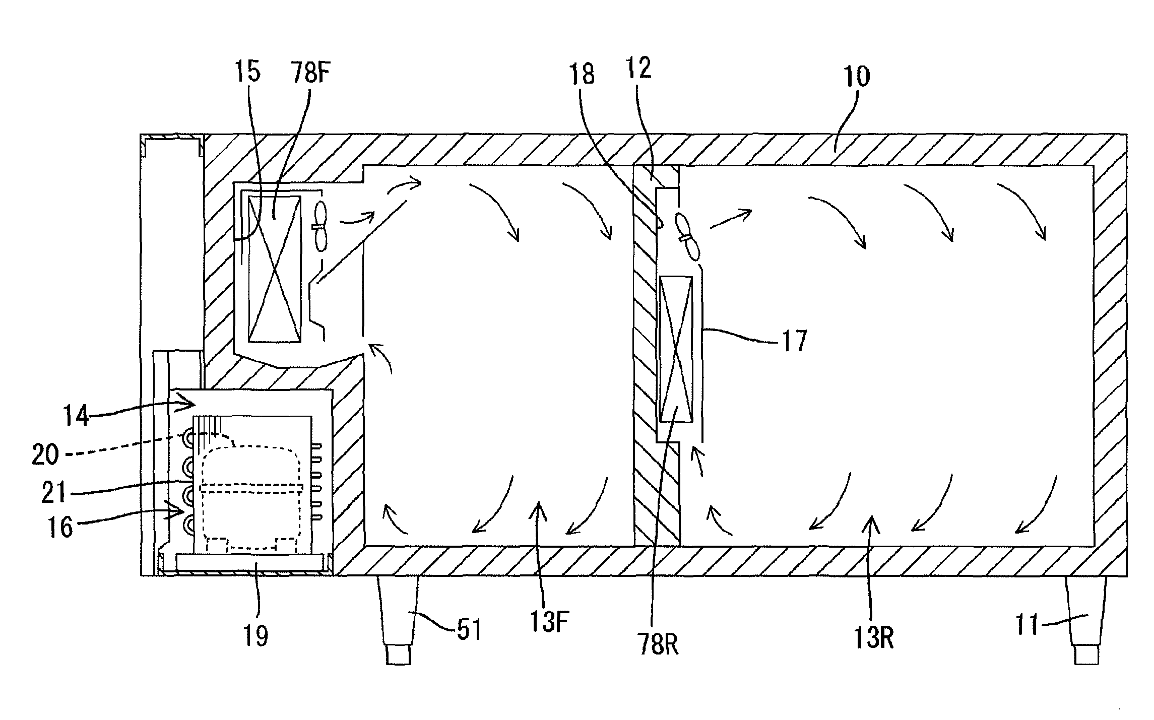
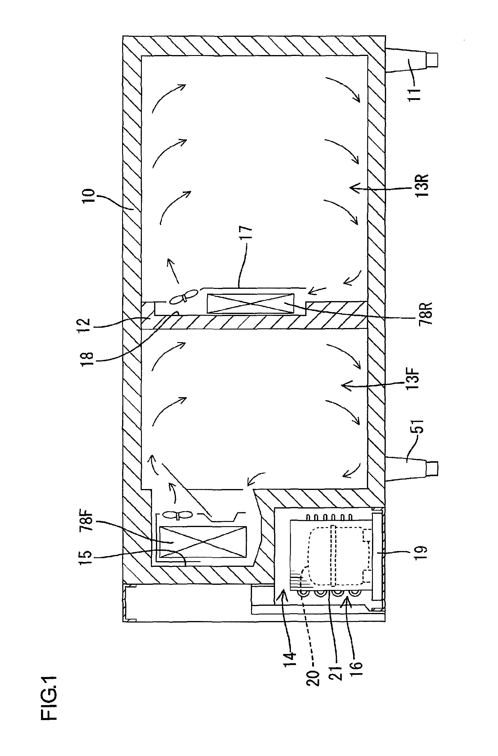
[0058]As referring now to FIGS. 1 to 6, Embodiment 1 according to the present invention is described. The present Embodiment 1 is illustrated by example by being applied to a commercial lateral (table type) refrigerator freezer, and its entire structure is described as referring firstly to FIG. 1. The symbol 10 represents a storage body, composed of a heat insulating box body that is horizontally long and opening in the front surface and supported by legs 11 provided in four corners on the bottom surface. The inside of the storage body 10 is divided into right and left sides by a heat insulating and post-installing partition wall 12, and the relatively narrower left side is a freezing room 13F corresponding to a first storage room, while the relatively wider right side is a refrigeration room 13R corresponding to a second storage room. In addition, though not shown, a heat insulating door is attached to the opening on the front surface of the freezing room 13F a...

embodiment 2

[0072][Embodiment 2 ]

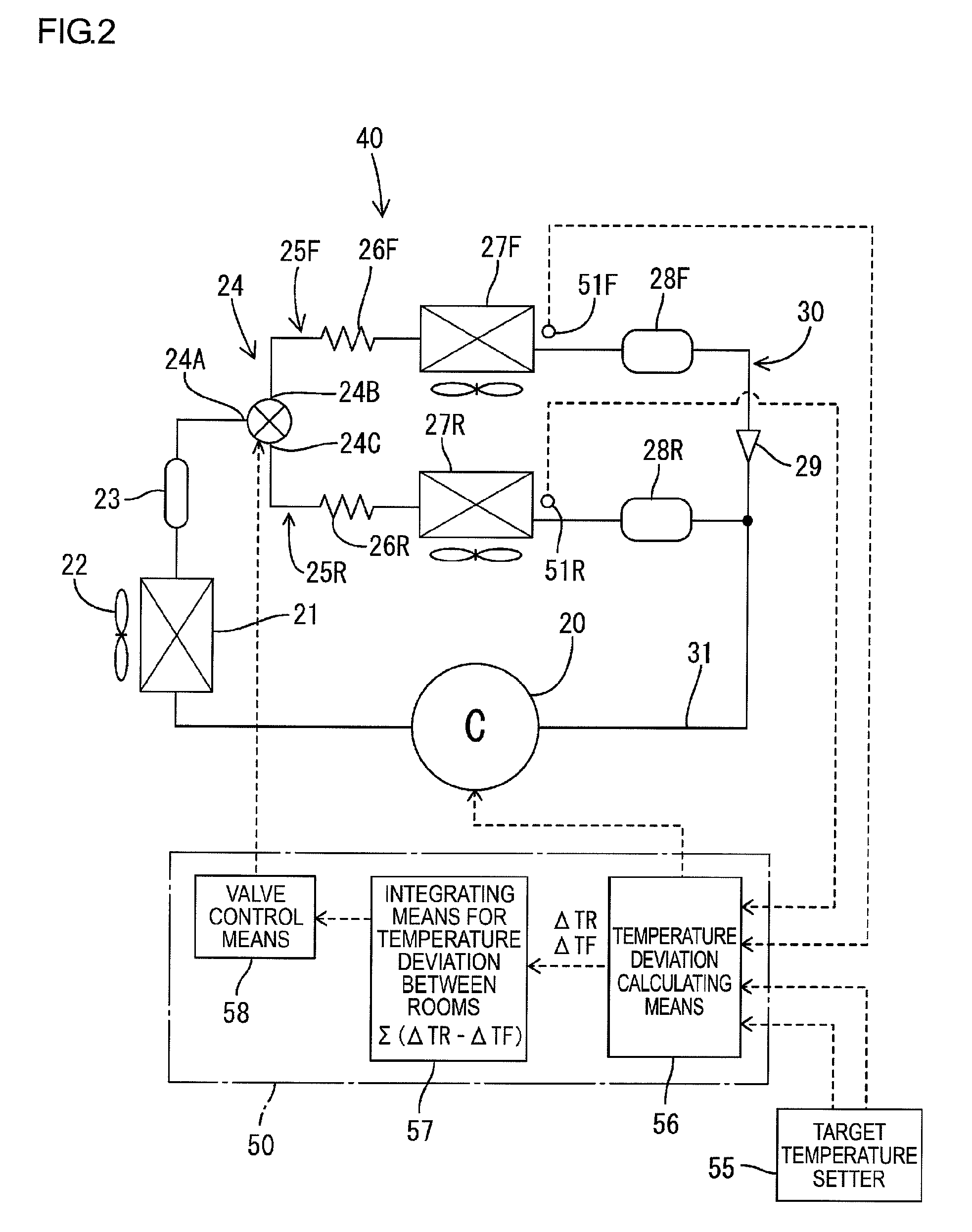
[0073]In the above-mentioned Embodiment 1, the target temperature setter 55 outputs a signal corresponding to the constant lower limit set temperatures TF(OFF) and TR(OFF) that do not change temporally, and the cooling is controlled with these constant set temperatures as a target in both the pull-down operation for cooling the storage room temperature of each storage room 13F and 13R from the room air temperature zone to around each set temperature and in the afterward control operation for keeping the storage room temperature at a set temperature. However, in Embodiment 2, the target temperature setter is constituted so as to sequentially output a different target temperature with the lapse of time.

[0074]In other words, each target temperature of the freezing room 13F and the refrigeration room 13R is provided as a temporal changing mode (in short, a mode for changing the target temperature along with the time t). As the changing mode of the target temperature...

embodiment 3

[0076][Embodiment 3 ]

[0077]In the above Embodiments 1 and 2, the compressor 20 of a fixed speed type is used as example, however, the compressor 20 may be a variable speed type driven by an inverter motor, so that the performance of the refrigerating cycle 40 can be adjusted. An embodiment thereof is described as Embodiment 3 in reference to FIGS. 7 to 10.

[0078]In the present embodiment, the difference from the above-mentioned Embodiments 1 and 2 is that the compressor 20 is driven by an inverter motor. The rotational speed of the inverter motor of the compressor 20 is controlled by for example a rotational speed controller 60 that comprises an inverter and outputs an AC of a variable frequency, and the rotational speed controller 60 is given a signal from a temperature deviation accumulated value calculator 70. And also, as in Embodiment 2, a target temperature setter 80 is constituted so as to sequentially output a different target temperature with the lapse of time. Other structu...


PUM


Abstract

The liquid refrigerant from the compressor 20 and the condenser 21 is alternately supplied to the cooling device for the freezing room 27F and the evaporator for the refrigeration room 27R through the three-way valve 24, so that the freezing room and the refrigeration room are alternately cooled. Here, the ratio of the refrigerant supply time to each evaporator is controlled based not on a deviation between a target temperature set for each storage room and an actual storage room temperature measured in each storage room, but on an integrated value obtained by integrating the difference of these deviations. In a cooling storage, in which from one compressor a refrigerant is selectively supplied to multiple evaporators respectively disposed in multiple storage rooms of varied thermal loads, a one-storage room cooling mode is prevented from being unnecessarily switched to a alternate cooling mode.

Description

TECHNICAL FIELD[0001]The present invention relates to a cooling storage which comprises multiple evaporators and supplies a refrigerant to these evaporators from one compressor, and an operating method of the same.BACKGROUND ART[0002]As one of this kind of cooling storages, for example, Patent literature 1 as below has been disclosed, in which heat insulating freezing room and refrigeration room are partitioned in a heat insulation storage body, while an evaporator is provided in each room, so that a refrigerant is alternately supplied to each of these evaporators from one compressor to produce cooling action.[0003]In this kind of refrigerator, a refrigerant is compressed by the compressor and then liquefied by the condenser, so as to be alternately supplied to the evaporator for freezing room and the evaporator for refrigeration room that are connected to the exit side of a three-way valve respectively via a capillary tube. At the time of so-called a control operation wherein a reg...

Claims


Application Information

Patent Timeline
Patent Type & Authority Patents(United States)
IPC IPC(8): F25B1/00
CPCF25B5/02F25B49/022F25D11/022F25B2600/2511F25D2400/08F25D17/067F25B2700/2117F25D2700/02F25D29/00F25D11/02
Inventor KONDOU, NAOSHIHIRANO, AKIHIKOYATORI, MASAHIDEKAGA, SHINICHITASHIRO, HIDEYUKI
Owner HOSHIZAKI ELECTRIC CO LTD
Why Eureka
Try Eureka