Bill and coin acceptor

a bill and coin technology, applied in the field of bill and coin receiving technology, can solve the problems achieve the effects of saving much management cost, widening the range of application, and simplifying design and fabrication

Inactive Publication Date: 2012-07-03
INT CURRENCY TECH
View PDF4 Cites 1 Cited by
  • Summary
  • Abstract
  • Description
  • Claims
  • Application Information

AI Technical Summary

Benefits of technology

[0009]Further, the face panel has a bill slot, a coin slot and a coin-return slot. The first housing and the second housing define therebetween a bill passage in communication with the bill slot. The first housing comprises a bill passage, a power drive mechanism adapted for transferring an inserted bill from the bill slot through the bill passage and a bill recognition module adapted for recognizing the authenticity and value of an inserted bill. The second housing comprises a coin passage in communication with the coin slot, a coin sensor module and an optical recognition device adapted for sensing the authenticity and value of an inserted coin, a driven gear set for assisting transfer of an inserted bill through the bill passage, a coin-return passage in communication with the coin-return slot and a gate movable by an electromagnetic valve to open the passage between the coin passage and the coin-return passage. Thus, the bill and coin acceptor can be used in a host for unmanned operation and customer self service, saving much the management cost.
[0010]Further, after mounting of the face panel on the first housing and the second housing, the compact-sized bill and coin acceptor can then be directly mounted in a host, keeping the bill passage and the coin passage in communication with corresponding internal passages of the host for enabling the host to accept bills and coins. Thus, using the bill and coin acceptor in a host needs not to change the specifications of the host. Therefore, the invention simplifies the design and fabrication of the whole system, and greatly widens its application range.

Problems solved by technology

Thus, the bill and coin acceptor can be used in a host for unmanned operation and customer self service, saving much the management cost.

Method used


Image

  • Bill and coin acceptor
  • Bill and coin acceptor
  • Bill and coin acceptor

Examples


Embodiment Construction

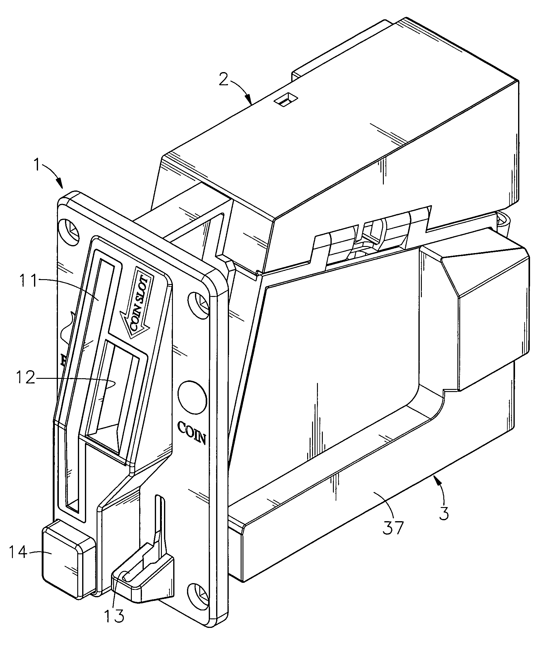
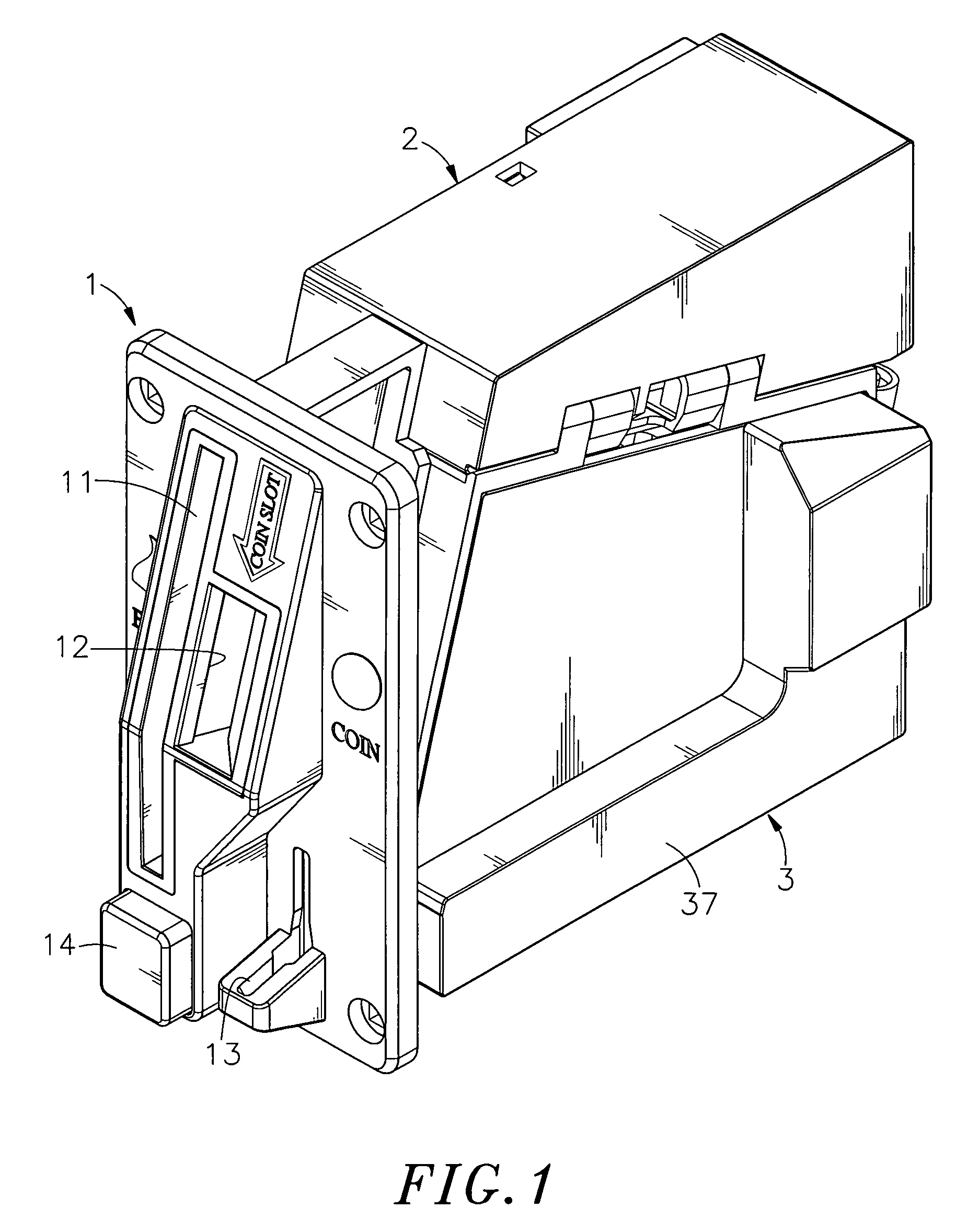
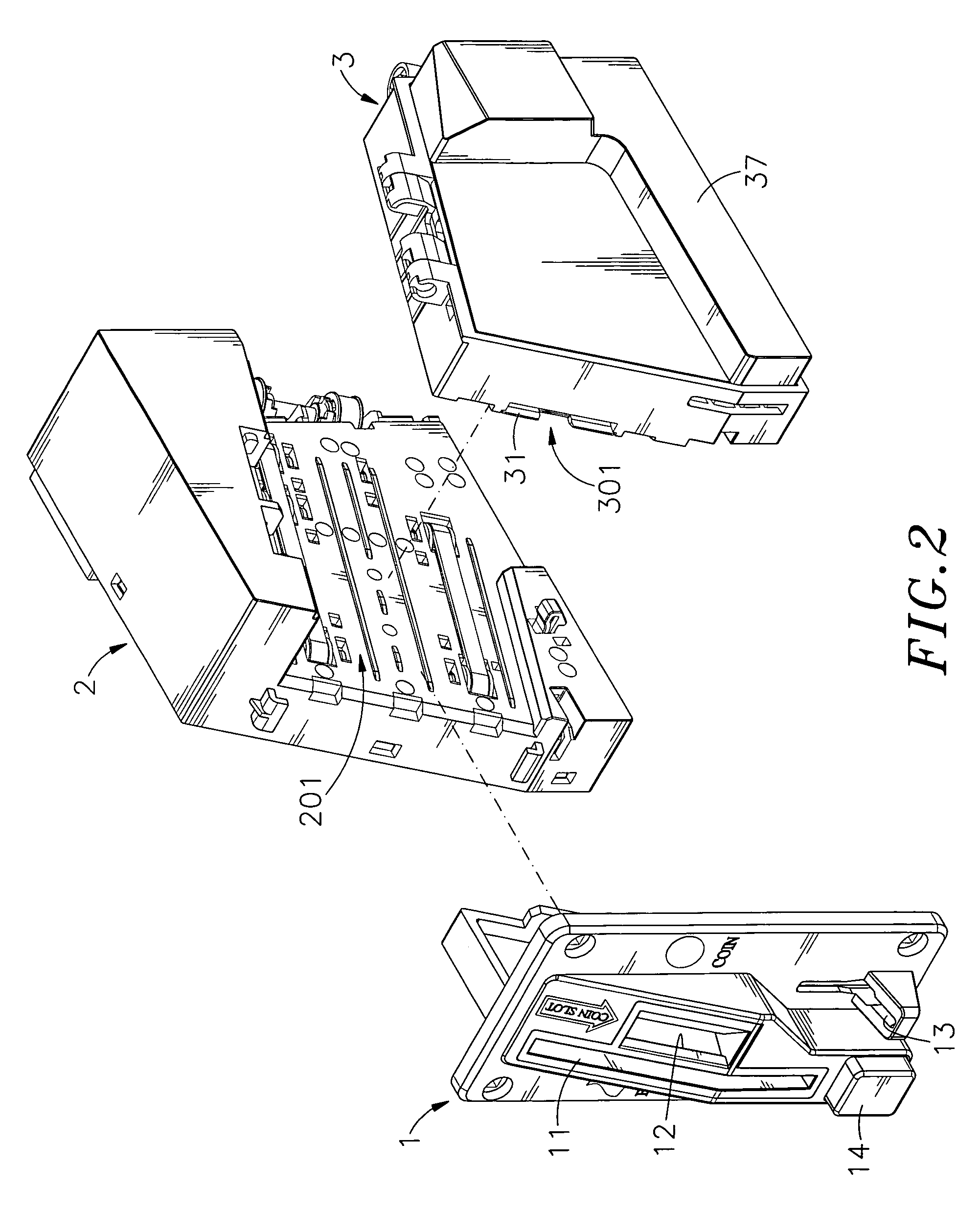
[0019]Referring to FIGS. 1˜4, a bill and coin acceptor in accordance with the present invention is shown comprising a face panel 1, a first housing 2 and a second housing 3.

[0020]The face panel 1 comprises a bill slot 11, a coin slot 12 cut disposed adjacent to the bill slot 11 at one lateral side, a coin-return slot 13 spaced below the coin slot 12, and a coin-release button 14 arranged at the front side.

[0021]The first housing 2 houses a bill-receiving module 20. Further, the first housing 2 has opposing inner and outer lateral sides and defines a bill passage 201 at the inner lateral side. The bill-receiving module 20 comprises a power drive mechanism 21, a bill recognition module 22, an outer cover 23, a circuit module 24 and a bill-expelling mechanism 25. The power drive mechanism 21 comprises a motor 211, a drive gear set 212 coupled to and rotatable by the motor 211, and bill-transfer belts 213 mounted on the drive gear set 212 and rotatable by the drive gear set 212 to trans...


PUM


Abstract

A compact size bill and coin acceptor for use in an automatic vending machine or game machine is disclosed to include a face panel having a bill slot, a coin slot and a coin-return slot, a first housing that comprises a bill passage, a power drive mechanism adapted for transferring an inserted bill from the bill slot through the bill passage and a bill recognition module adapted for recognizing the authenticity and value of an inserted bill, and a second housing that comprises a coin passage in communication with the coin slot, a coin sensor module and an optical recognition device adapted for sensing the authenticity and value of an inserted coin, a driven gear set for assisting transfer of an inserted bill through the bill passage, a coin-return passage in communication with the coin-return slot and a gate movable by an electromagnetic valve to open the passage between the coin passage and the coin-return passage.

Description

BACKGROUND OF THE INVENTION[0001]1. Field of the Invention[0002]The present invention relates to bill and coin receiving technology and more particularly, to a bill and coil acceptor, which has a compact size for easy installation in a host with less space occupation, for enabling the host to accept bills and coins.[0003]2. Description of the Related Art[0004]Following fast development of modern technology, the pace of every day life has speeded up everything from faster fast food in our own neighborhood to instant communication across the world. Nowadays, non-shop business has become popular, and various automatic vending machines (card dispensers, ticket vending machines, coin exchanging machines, etc.) are used everywhere to sell different products without serviceman. The use of automatic vending machines creates new marketing routes for the suppliers, saves much labor cost, and brings convenience to consumers.[0005]Further, an automatic vending machine or game machine has a coin...

Claims


Application Information

Patent Timeline
Patent Type & Authority Patents(United States)
IPC IPC(8): G07F1/00G07F1/02G07F7/04
CPCG07D5/08G07D7/12
Inventor CHANG, YU-TSUNG
Owner INT CURRENCY TECH
Why Eureka
Try Eureka