Method of fabricating electrode catalyst layers with directionally oriented carbon support for proton exchange membrane fuel cell

a proton exchange membrane fuel cell and electrode catalyst technology, applied in the manufacture of final products, cell components, electrochemical generators, etc., can solve the problems of high precious metal usage, inaccessible gas flow, inefficient utilization, etc., and achieve the effect of simplifying the design and fabrication of bipolar plates and reducing precious metal usag

Inactive Publication Date: 2006-11-30
UCHICAGO ARGONNE LLC +1
View PDF8 Cites 46 Cited by
  • Summary
  • Abstract
  • Description
  • Claims
  • Application Information

AI Technical Summary

Benefits of technology

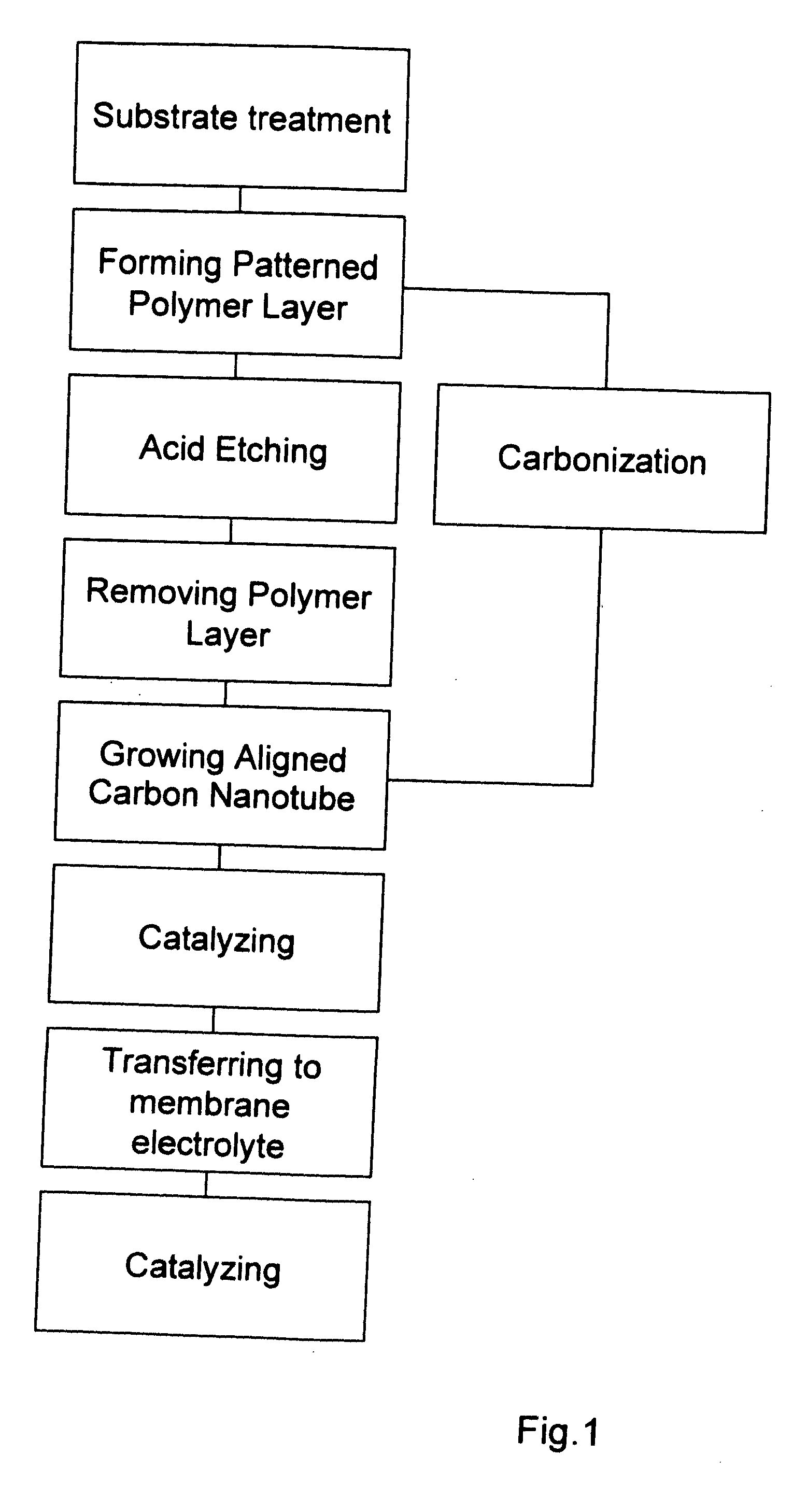
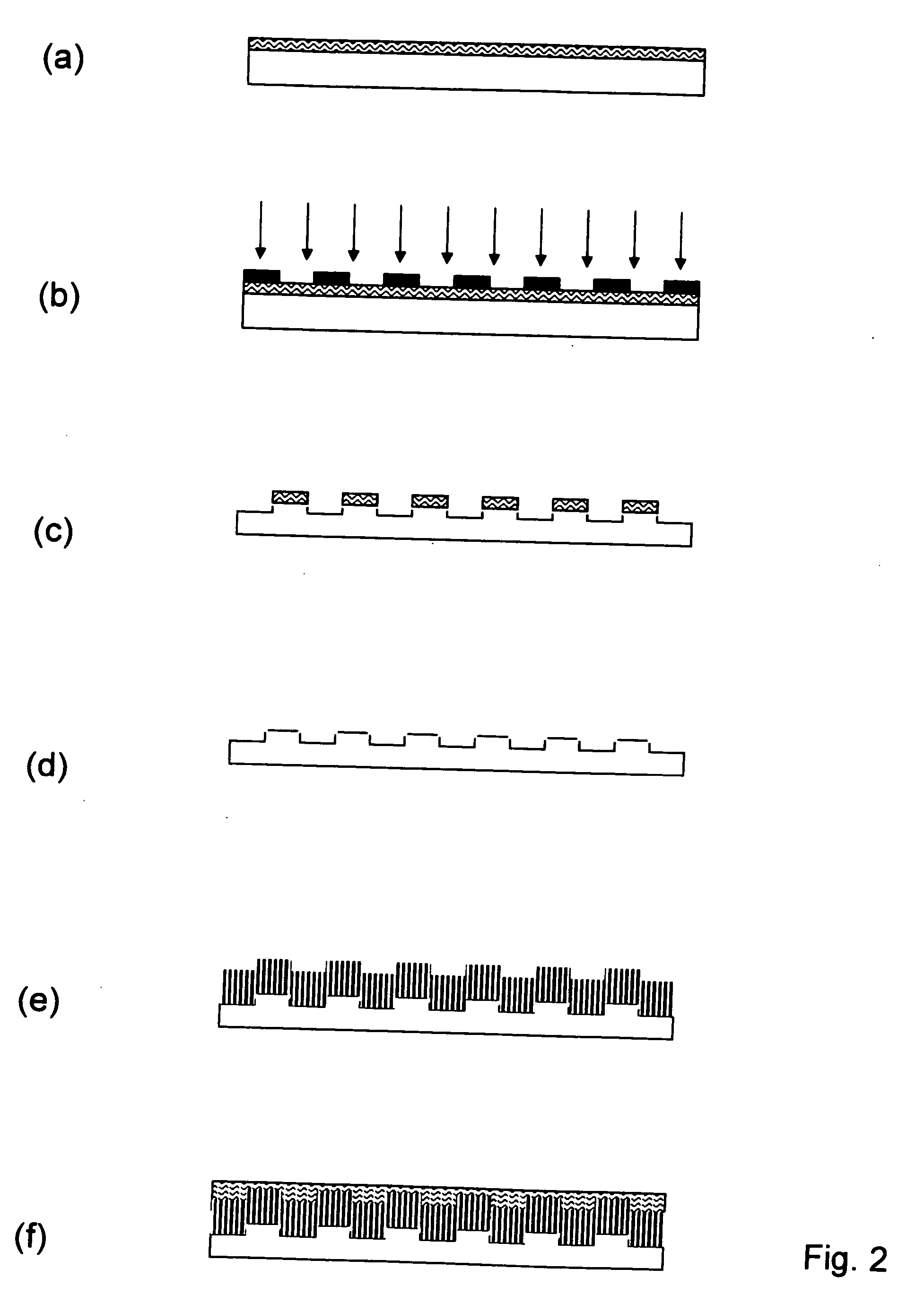
[0010] This invention relates to a new method of preparing a membrane electrode assembly (MEA) for a PEMFC that reduces precious metal usage, eliminates the need for GDE and simplifies the design and fabrication of bipolar plates. The inventive method consists of multiple steps including growing template-free aligned carbon nanotubes, transferring directionally aligned nanotubes onto the surface of a polymer electrolyte, and fabricating a fuel cell with flow field-free bipolar plates. This new method also leads to a new PEM fuel cell design in which either or both anode and cathode are made of aligned carbon nanotubes with a portion of the nanotubes embedded in a proton conduction polymer and another portion exposed to reactant gas flow contacting the bipolar plates directly. The aligned nanotubes can also be built optionally with a pre-designed flow field pattern. MEA design eliminates the need for GDE and the necessity of embossing flow fields on the surface of bipolar plates.
[0017] Another object of the invention is to provide a MEA containing aligned carbon nanotubes with 3-D pattern on one or both sides of the electrolyte membrane and perpendicular thereto and may function as flow fields for reactant gases to improve the electric conductivity or the distribution of gases. The aligned carbon nanotubes can be used as the support for electrode catalysts or have electrocatalytic function for an oxygen reduction reaction.
[0018] A final object of the invention is to provide PEM fuel cells wherein the inventive MEA remove the need of embossing a flow field on the bipolar plates. Furthermore, graphitic carbon nanotubes contact directly the bipolar plates with improved electric conductivity and remove the need of a gas distribution electrode (GDE). Such improvements simplify the PEM fuel cell manufacturing process and reduce the cost.

Problems solved by technology

One of the contributing causes of high precious metal usage is inefficient utilization of the precious metal the the present electrode catalyst preparation method.
An intrinsic limitation to this approach is that a significant amount of catalyst is embedded underneath of the polymer matrix during the hot-pressing, rendering it inaccessible to gas flow.
A GDE adds additional manufacturing cost and complexity to a PEMFC fabrication.
Construction of a flow field on a bipolar plate adds cost and complexity to the PEMFC fabrication process.
The prior art requiring alumina templates does not have this flexibility.

Method used


Image

  • Method of fabricating electrode catalyst layers with directionally oriented carbon support for proton exchange membrane fuel cell
  • Method of fabricating electrode catalyst layers with directionally oriented carbon support for proton exchange membrane fuel cell
  • Method of fabricating electrode catalyst layers with directionally oriented carbon support for proton exchange membrane fuel cell

Examples


example 1

[0040] A thin quartz plate with dimension of ⅝″×1.5″×0.1″ was cleaned in a solution containing 70 vol. % concentrated H2SO4 and 30 vol. % H2O2. The solution temperature was maintained between 70° C. to 100° C. After cleaning and rising with deionized water, it was ultrasonically cleaned in acetone for 30 min. The dried quartz plate was ready for the use as the substrate.

example 2

[0041] A negative photo-resist solution was prepared by mixing the solution A and B where A is made by dissolving 184 mg of Triphenylsulfonium triflate in 12 ml water / acetonitrile solution followed by mixing with 725 mg of N-(Hydroxymethyl)acrylamide solution, and B was made by dissolving 2.029 g PVA in 20 ml water. The photo-resist solution was subsequently filtered through a 0.1 μm filtration paper and used for spin-coating on the treated quartz substrate according to Example 1 with a high speed spin-coater (Model 1—EC11DT-R485, Headway research, Inc.). A pipette was filled with the photo-resist solution. The solution was dispensed over the quartz substrate in a droplet fashion while the coater spun at 2500 rpm for 30 seconds. The coating was baked at 90° C. for 30 minutes inside of a vacuum oven. A photo-mask with linear strip pattern was placed over the top of the coated quartz plate. An ultraviolet radiation with wavelength of 254 nm generated from an UV lamp (Mineralight, UVG-...

example 3

[0042] A positive photo-resist solution was obtained under the brand name Shipley S1818, that contains diazonapthoquinone and Novalac resin dissolved in propylene glycol methyl ether acetate. The substrate prepared according to the Example 1 was first coated by a thin layer of hexamethyldisilazane (HMDS) via a spin coater before being coated with the photo-resist solution with the dry thickness about 2 μm. After baking in vacuum oven at 90° C. for 30 minutes, a photo-mask with linear strip pattern was placed over the top of coated substrate plate. An ultraviolet radiation with wavelength of 365 nm generated from an UV lamp (Ultra Violet Products, Model UVL-23RW) was applied to the coated plate through the photo-mask for 15 seconds. The exposed substrate was subsequently developed in an aqueous solution containing 5% tetramethylammonium hydroxide for 1 minute followed by rinsing in deionized water to wash away the exposed portion of the coating. After baking at 130° C. for 30 minutes...


PUM

PropertyMeasurementUnit
temperatureaaaaaaaaaa

Abstract

A method of making a membrane electrode assembly (MEA) having an anode and a cathode and a proton conductive membrane there between. A bundle of longitudinally aligned carbon nanotubes with a catalytically active transition metal incorporated in the nanotubes forms at least one portion of the MEA and is in contact with the membrane. A combination selected from one or more of a hydrocarbon and an organometallic compound containing an catalytically active transition metal and a nitrogen containing compound and an inert gas and a reducing gas is introduced into a first reaction zone maintained at a first reaction temperature for a time sufficient to vaporize material therein. The vaporized material is transmitted to a second reaction zone maintained at a second reaction temperature for a time sufficient to grow longitudinally aligned carbon nanotubes with a catalytically active transition metal incorporated throughout the nanotubes. The nanotubes are in contact with a portion of the MEA at production or being positioned in contact thereafter. Methods of forming a PEMFC are also disclosed.

Description

RELATED APPLICATIONS [0001] This application, pursuant to 37 C.F.R. § 1.78©, claims priority based on provisional application Ser. No. 60 / 684,864 filed May 26, 2005.CONTRACTUAL ORIGIN OF THE INVENTION [0002] The United States Government has rights in this invention pursuant to Contract No. W-31-109-ENG-38 between the U.S. Department of Energy (DOE) and The University of Chicago representing Argonne National Laboratory.FIELD OF THE INVENTION [0003] This invention relates to the preparation of aligned carbon nanotubes with transition metal catalyst sites longitudinally spaced therealong and is related to Provisional Application Ser. No. 60 / 692,773, filed Jun. 21, 2005, to which the non-provisional application Serial No. ______ filed ______, is being filed concurrently herewith, the entire disclosure thereof being incorporated by reference. BACKGROUND INFORMATION [0004] The proton exchange membrane fuel cell (PEMFC) continues to benefit from intense development efforts for its potentia...

Claims


Application Information

Patent Timeline
Patent Type & Authority Applications(United States)
IPC IPC(8): H01M8/10H01M4/00
CPCH01M4/9008H01M8/04194Y10T428/30H01M2008/1095Y02E60/521H01M8/1004Y02E60/50Y02P70/50
Inventor LIU, DI-JIAYANG, JUNBING
Owner UCHICAGO ARGONNE LLC
Why Eureka
Try Eureka