Fuel circuit of a turbine engine

a turbine engine and fuel circuit technology, applied in the direction of turbine/propulsion fuel valves, efficient propulsion technologies, machines/engines, etc., to achieve the effects of simple, compact, and limited weight, and simplify the design and fabrication of elements of the main circui

Active Publication Date: 2017-05-16
SN DETUDE & DE CONSTR DE MOTEURS DAVIATION S N E C M A
View PDF8 Cites 8 Cited by
  • Summary
  • Abstract
  • Description
  • Claims
  • Application Information

AI Technical Summary

Benefits of technology

[0018]Compared with other solutions, the solution described presents the advantage of being simple, compact (an aspect that is important in turbojets of the most recent generation), and of limited weight.
[0019]In particular, it makes it possible to simplify the design and the fabrication of elements of the main circuit. For example, compared with the prior art example of FIG. 1, the present solution simplifies the design and the fabrication of the LP pump, since it is no longer necessary to associate a filter with this pump or with any other equipment in the main circuit (thereby economizing on an interface and a pipe). Also, the fuel fed to the FRV may be taken from the main fuel circuit independently of the presence and / or the position of any filters (and in particular of the main filter) in the main circuit. Finally, since the first and second filters are dedicated only to filtering the fuel being fed to the FRV, the degree of filtration they provide can be determined depending on the needs specific to the FRV, and this degree of filtration has no effect on the filtering cascade in the main circuit. The fact that the fuel is filtered depending on the needs specific to the FRV can also make it possible to simplify the design of the FRV, thus leading to a saving in weight and an improvement in lifetime.
[0020]The present solution also avoids any need to incorporate a self-cleaning filter in the FRV. A filter incorporated in the FRV would present drawbacks since the FRV is mounted on the turbine engine at a relatively large distance from the main fuel circuit. Consequently, if a self-cleaning filter were incorporated in the FRV, it would be necessary to provide a long circuit loop connected to the main circuit and going to the self-cleaning filter in order to clean it. However, such an additional long loop would give rise to problems of weight and bulk.
[0021]Finally, the present solution also creates a flow of recirculated fuel when the FRV is closed, i.e. when the fuel circuit is in a “cold” condition. This may be considered as being an advantage when dimensioning the heat exchanger that is to be found in this recirculation and that is then used for heating the fuel. This also makes it possible to cool the FRV while performing tests on its ability to withstand fire while the FRV is in the closed position.
[0022]It should be observed that the degree of filtration of the first and second filters must be sufficiently small to be suitable for protecting the FRV effectively. This degree of filtration is typically less than or equal to 50 micrometers (μm), and is preferably about 45 μm. However, the smaller the degree of filtration, the quicker the filter becomes clogged and the greater the amount of cleaning required by the first and second filters.
[0023]The fact that the first and second filters are cleaned when the FRV is closed greatly reduces, and generally even eliminates, any risk of the filters clogging. There is therefore no need to provide a bypass system for bypassing each filter in the event of clogging. Furthermore, since the FRV is generally used only under conditions where the fuel is hot, there is no risk of the filter icing, and there is therefore no need to provide a bypass system for bypassing the filter in the event of icing. Also, and advantageously, the circuit does not have any bypass systems for bypassing the first and second filters. This enables the design of the circuit to be simplified and its weight and bulk to be reduced.

Problems solved by technology

Since the operating clearances in an FRV are small, they are particularly sensitive to clogging and also to wear, and they therefore need to be protected against the impurities present in the fuel.

Method used


Image

  • Fuel circuit of a turbine engine
  • Fuel circuit of a turbine engine
  • Fuel circuit of a turbine engine

Examples


Embodiment Construction

)

[0042]Embodiments are described in detail below, with reference to the accompanying drawings. These examples show the characteristics and the advantages of the invention. Nevertheless, it should be recalled that the invention is not limited to these examples.

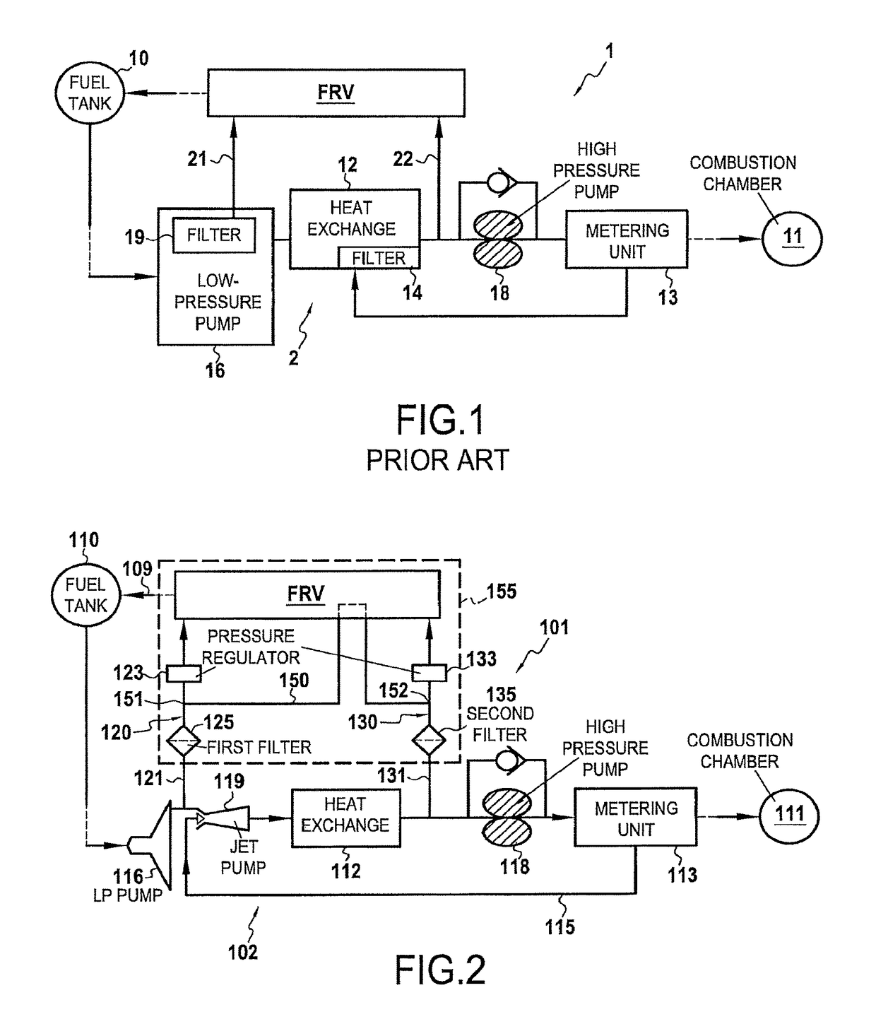
[0043]FIG. 1 shows a prior art example of an airplane turbine engine fuel circuit. This prior art circuit is described above.

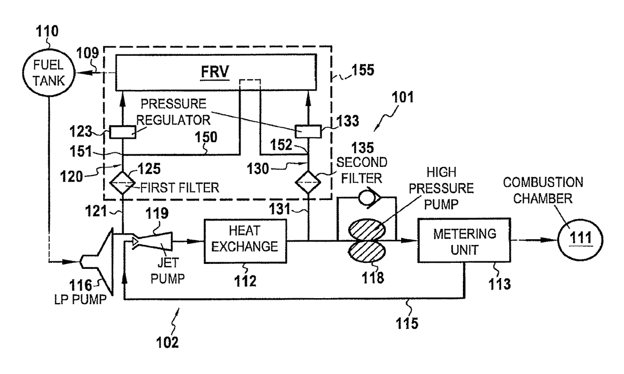
[0044]FIG. 2 shows a fuel circuit 101 for a turbine engine, more particularly for an airplane turbojet. The circuit 101 comprises a main circuit 102 extending between the fuel tank 110 of the airplane and the combustion chamber 111 of the turbojet.

[0045]Going from upstream to downstream, the main circuit 102 comprises: a low-pressure pump (or LP pump) 116 connected to the tank 110; a jet pump 119; a heat exchanger 112; a high-pressure pump (or HP pump) 118; and a metering unit 113 for feeding fuel to the combustion chamber 111. A filter (not shown) may be provided between the HP pump 118 and the metering ...


PUM


Abstract

A fuel circuit for a turbine engine is provided. The fuel circuit includes a fuel return valve connected to the main circuit and to a fuel tank, the valve being capable of adopting an open position in which the valve allows an excess quantity of fuel to be returned to the tank, and a closed configuration in which the return of fuel to the tank is blocked; a first hydraulic line connecting the valve to the main circuit, and including a first filter; a second hydraulic line connecting the valve to the main circuit, and including a second filter; and an intermediate hydraulic line connected to the first and second lines downstream from the filters, the first and second lines being hydraulically connected together by the intermediate line when the valve is in the closed configuration.

Description

FIELD OF THE INVENTION[0001]The present description relates to a fuel circuit of a turbine engine, and to a turbine engine including such a circuit.[0002]By way of example, it may be a fuel circuit of a turbine engine for use on land or in aviation (turbojet or turboprop) and, more particularly, it may be a fuel circuit of an airplane turbojet.STATE OF THE PRIOR ART[0003]A known example of an airplane turbojet fuel circuit is shown in accompanying FIG. 1. The circuit 1 comprises a main circuit 2 with a low-pressure pump 16 connected to the fuel tank 10 of the airplane, a high-pressure pump 18, a heat exchanger 12, and a metering unit 13 for feeding fuel to the combustion chamber 11. The circuit 1 also incorporates a fuel return valve (FRV).[0004]The purpose of the FRV is to return a certain quantity of hot excess fuel 22 (referred to as “hot” fuel) that has passed through the heat exchanger 12 back to the tank 10 in order to improve the thermal equilibrium of the system. FRVs are ap...

Claims


Application Information

Patent Timeline
Patent Type & Authority Patents(United States)
IPC IPC(8): F02C7/22F02C9/36F02C7/232F02C7/236F02C9/26
CPCF02C7/22F02C7/232F02C7/236F02C9/26F02C9/263F02C9/36F05D2260/601F05D2260/606F05D2260/607Y02T50/671Y02T50/675Y02T50/60
Inventor VERTENOEUIL, PHILIPPEBRUN, GILLES
Owner SN DETUDE & DE CONSTR DE MOTEURS DAVIATION S N E C M A
Why Eureka
Try Eureka