Width-adjustable product display tray with novel mounting arrangement

a product display tray and mounting arrangement technology, which is applied in the direction of show hangers, kitchen equipment, show cabinets, etc., can solve the problems of affecting the merchandiser's business, so as to facilitate the positioning and adjustment of the trays, easy and quick placement, and easy to adjust the widthwise

Active Publication Date: 2012-07-03
TRION IND
View PDF20 Cites 60 Cited by
  • Summary
  • Abstract
  • Description
  • Claims
  • Application Information

AI Technical Summary

Benefits of technology

[0004]The present invention is directed to an improved form of product display tray of the type having adjustable side guides and a spring actuated pusher arrangement, in which basic components of the tray can be of standardized design with specific modifications to enable the tray to be supported at its back end by means of a gondola-mounted display bar. The arrangement greatly facilitates positioning and adjustment of the trays in an overall display arrangement, and allows for the desired width adjustment of the tray to accommodate different sized products.
[0005]The display tray of the invention is adapted and intended for mounting on a display bar of the general type illustrated in U.S. Pat. No. 7,438,628, by way of example. Pursuant to the invention, the adjustable side guides of the tray, typically formed of wire, are formed of panels of rigid sheet material, preferably sheet metal. The panels are formed at the back end with downwardly opening, shaped recesses configured to fit closely over the cross section of a mounting bar of the type mentioned above, which serves to support the display tray in an outwardly projecting, cantilever fashion. The arrangement is such that the tray may be easily and quickly placed on the mounting bar and may be laterally positioned thereon by simply sliding the tray to one side or the other. The side guide panels, which serve to mount the tray, can be readily adjusted widthwise, with respect to the central portions of the tray, to accommodate different products.

Problems solved by technology

Historically, this has required the merchandisers to invest in and maintain a wide variety of different display systems, which represents significant cost and inconvenience to the merchandiser.

Method used


Image

  • Width-adjustable product display tray with novel mounting arrangement
  • Width-adjustable product display tray with novel mounting arrangement
  • Width-adjustable product display tray with novel mounting arrangement

Examples


Embodiment Construction

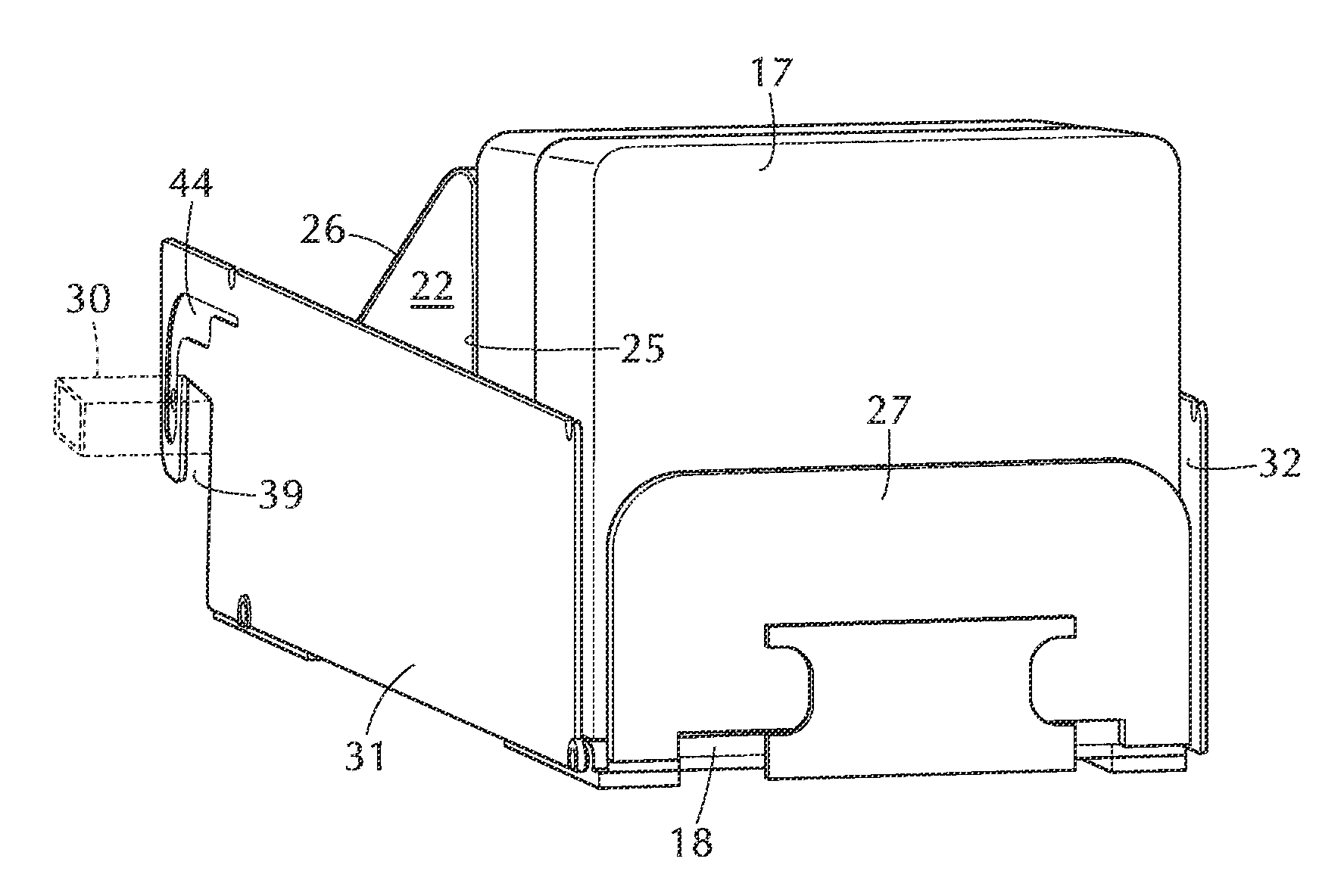
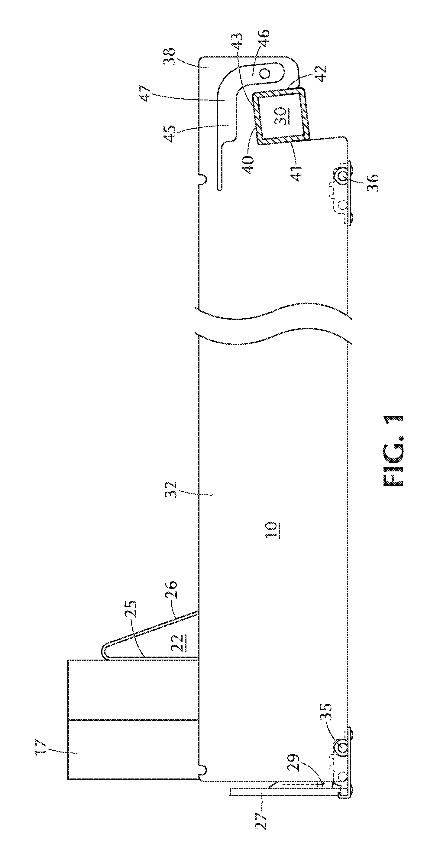
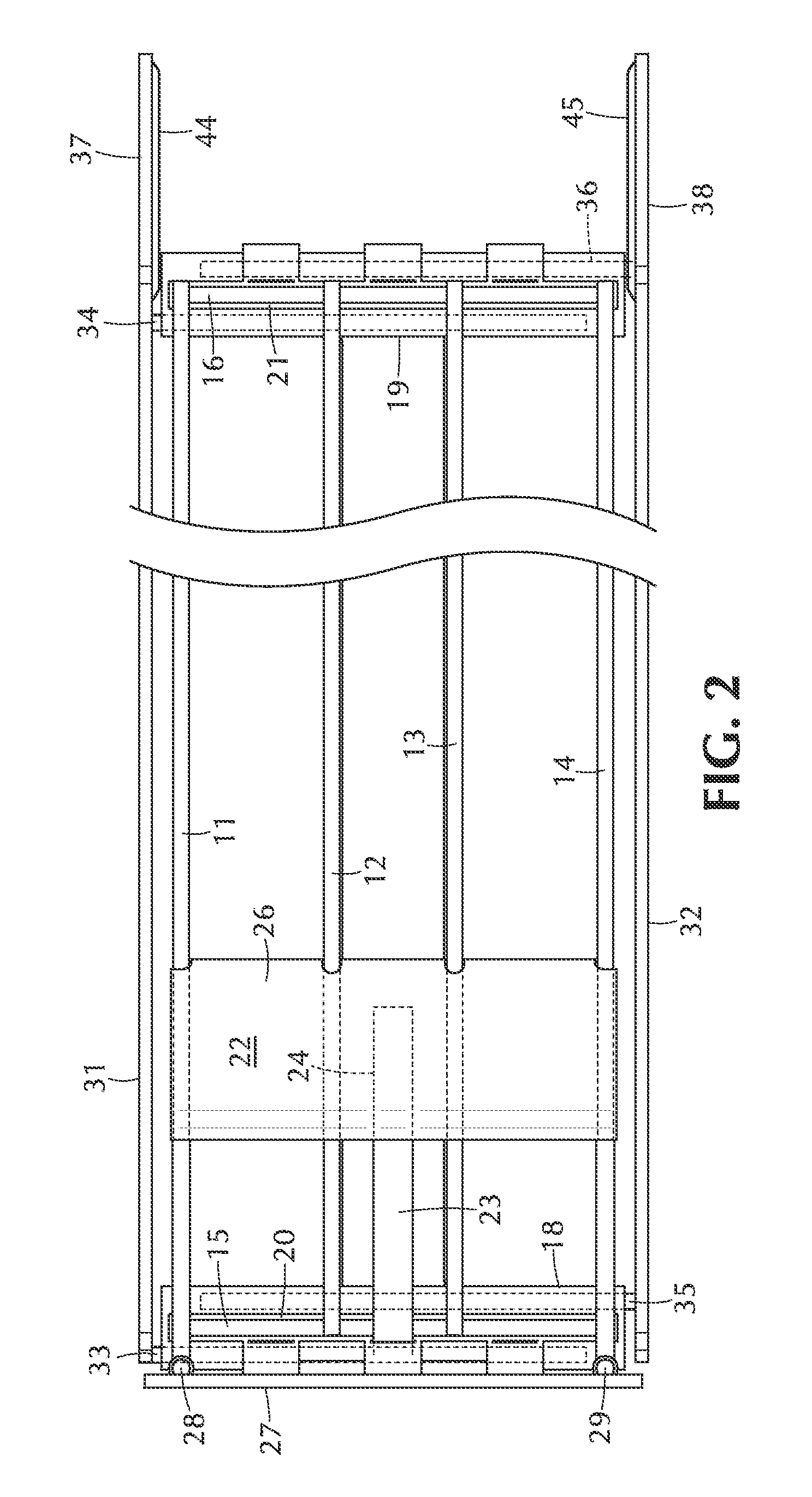
[0010]Referring now to the drawings, the reference numeral 10 designates generally a product display tray of the general type referred to in the before mentioned patents. The tray 10 includes a base structure which is advantageously in the form of a plurality of longitudinally extending wires 11-14, rigidly connected at the front and back to cross bars 15, 16. The longitudinal wires 11-14 and cross bars 15, 16 form a rigid base structure for the slideable support of display products 17. Front and back base members 18, 19, advantageously formed of plastic material, are formed with upwardly facing grooves 20, 21 for the snap-in reception of the cross bars 15, 16 respectively. A pusher element 22 is slideably engaged with the longitudinal wires 11-14 and is constantly urged forwardly by a coil spring element 23, the coiled portion 24 of which is contained between front and back walls 25, 26 of the pusher element.

[0011]Typically, the tray 10 is provided with a front barrier panel 27, wh...


PUM


Abstract

A display tray with a push-forward means for the display of product items in a back to front column, with the forwardmost item of the column being at all times urged tot the front of the tray. A special mounting arrangement is provided for the tray in which product side guides, preferably width adjustable, also serve to mount the trays on a rectangular bar positioned horizontally at the back of a display gondola or the like, enabling a plurality of such trays to be mounted side by side and movable laterally for desired spacing and appearance. To particular advantage, the side guides are formed of a rigid sheet material, typically sheet metal, provided at front and back portions with transverse mounting rods engageable with base members of the tray to accommodate lateral adjustment of the side guides relative to the central portions of the tray.

Description

BACKGROUND OF THE INVENTION[0001]In connection with the in-store display of small product items, it is a common practice to provide display trays arranged to receive a plurality of product items in a front-to-back column, with a spring actuated pusher arrangement at the back of the column for automatically moving the product column forward each time a product is removed from the front of the display. This provides a more sales-attractive display by keeping the merchandise always available at the front of the display where it is easily seen and easily removed.[0002]Inasmuch as products sold in such displays come in various sizes and shapes, it is typical to provide for width-adjustability of the trays to accommodate different types of products. Advantageous forms of display trays of this type are shown in U.S. Pat. Nos. 6,745,906, 6,866,155, 6,886,700, 6,889,855, and 7,032,761, owned by Trion Industries, Inc., assignee of this invention. The disclosures of these patents are incorpora...

Claims


Application Information

Patent Timeline
Patent Type & Authority Patents(United States)
IPC IPC(8): A47F5/08
CPCA47F1/125A47F3/14A47F5/0838
Inventor NAGEL, THOMAS O.KOLOGE, JOSEPH F.
Owner TRION IND
Why Eureka
Try Eureka