Performance oriented pail

a performance-oriented, pail technology, applied in the field of storage containers, can solve the problems of increasing the likelihood of failure, affecting the free flow of hazardous materials between countries, and thick sections found at the wall junctions of containers often experience a region of increased stress and an increased chance of structural failur

Inactive Publication Date: 2012-07-03
ROPAK CORP
View PDF64 Cites 42 Cited by
  • Summary
  • Abstract
  • Description
  • Claims
  • Application Information

AI Technical Summary

Problems solved by technology

In fact, as other countries adopted their own specifications, it became evident that without international standards, incompatible regulations could hinder the free flow of hazardous materials between countries.
However, in some cases, this design approach can actually lead to increases in the likelihood of a failure.
The thick sections found at the wall junctions of the container often experience a region of increased stress and an increased chance of structural failure when the container is subjected to a performance test or while in actual use.
This is due to the fact that during the injection molding process, the regions of increased thickness experience increased heating which, in turn, requires an increased amount of time to cool.
This often leads to weakness in the plastic that forms the wall junction.
Therefore, the sections of increased thickness found at the wall junction and other regions of the container can be prone to failure during performance tests or while in actual use.
Such benefits that result from using a reduced amount of material to produce the container cannot be realized, however, without design features that ensure the container can meet the standards required by the United Nations' regulations for dangerous goods and hazardous materials and thereby provide the safe transport of such materials.

Method used


Image

  • Performance oriented pail
  • Performance oriented pail
  • Performance oriented pail

Examples


Embodiment Construction

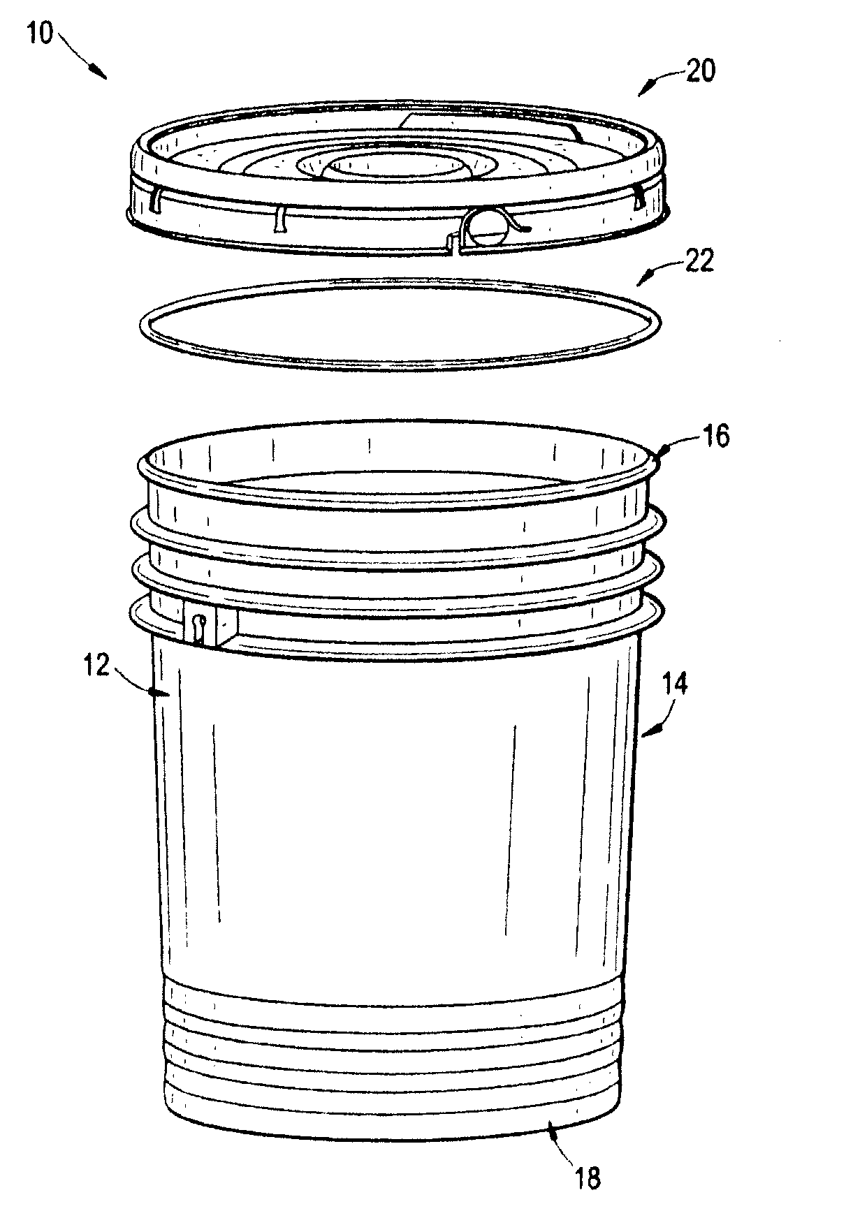
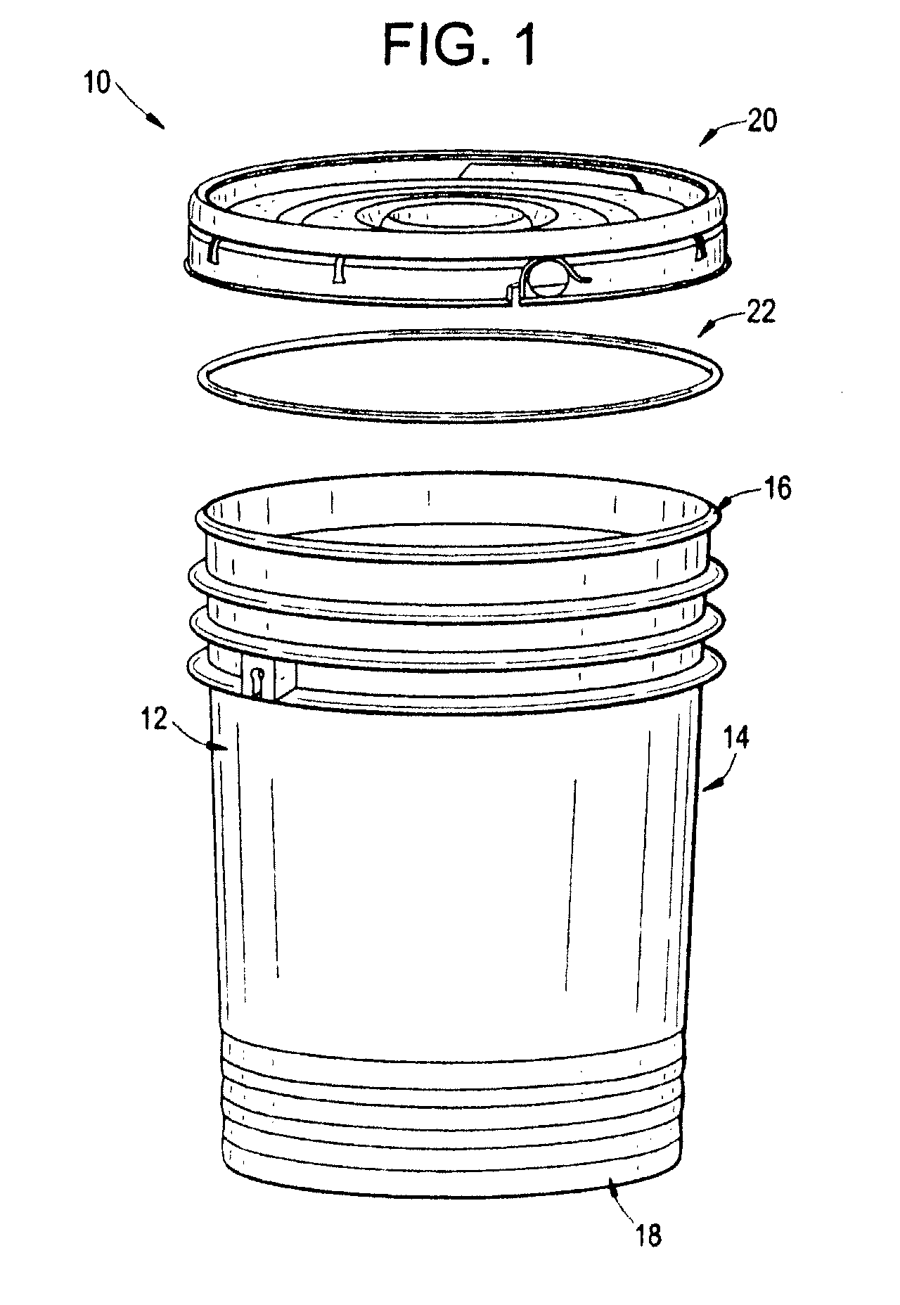
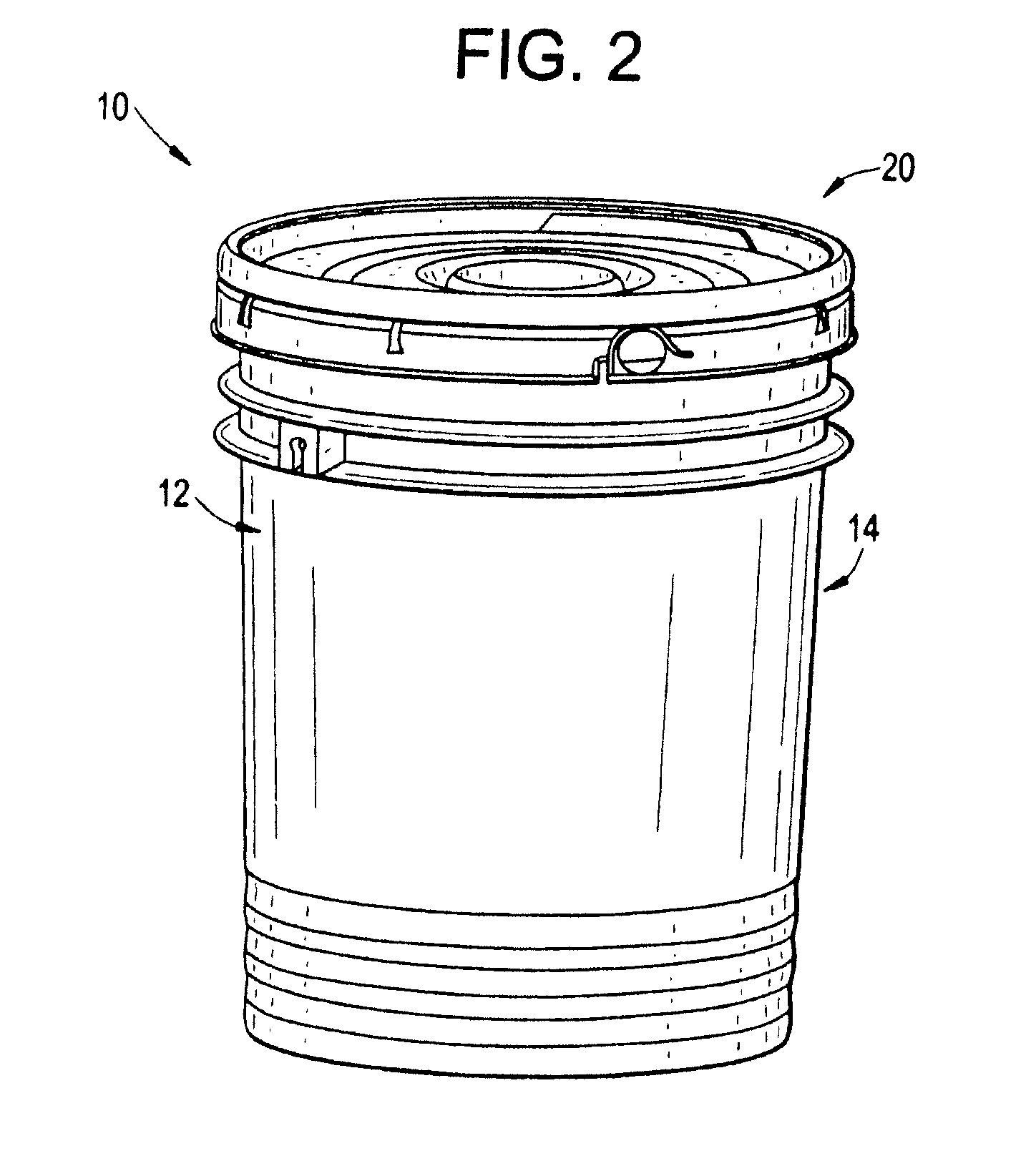
[0026]Turning in detail to FIGS. 1 and 2, an exemplary embodiment of a container 10 is illustrated. Container 10 comprises a pail 12 having a body 14 which forms an opening 16 at a proximal end and a closed floor or bottom 18 to seal a distal end of body 14, and an interlocking cover 20 to seal the open proximal end of pail 12. A tubular gasket 22 or other mechanism can be provided between the pail and cover to facilitate a tighter and more secure seal there between. Although the container can take on any number of different configurations, this particular embodiment illustrates pail 12 comprising a substantially cylindrical body 14. Body 14 and bottom 18 are typically formed as a single element (such as through a plastic injection molding process) to define an internal cavity that can be accessed through opening 16, thus allowing pail 12 to contain or store a variety of liquids and other materials.

[0027]Turning in detail to FIGS. 3 and 4, pail 12 comprises an angled bead 24 for int...


PUM


Abstract

A container comprising a pail, removable cover, and a gasket disposed between the cover and the pail is disclosed. The pail has an angled bead at the proximal end of the pail and a plurality of satellite rings that extend circumferentially around the pail and form a wall junction with the pail. The wall junction has a substantially constant wall thickness. A bail ear is formed to connect at least two of the satellite rings to define an opening between the bail ear and the body. The pail also includes a shock absorbing wall section.

Description

BACKGROUND[0001]1. Field of the Inventions[0002]The field of the invention relates generally to storage containers, and more particularly, to an improved injection molded container that can be used for the transport of dangerous goods and hazardous materials.[0003]2. Background Information[0004]Containers such as buckets and pails are known and used in a variety of shapes and sizes to store various materials. A conventional container is comprised of a cylindrical structure with an interior cavity that is closed at one end. The container may also include a removable cover to secure or close the upper opening of the container. A tubular gasket can also be disposed between the upper bead of the container and the cover to provide an improved seal. A handle may also be attached to the container to help facilitate the carrying and handling of the container.[0005]Despite the broad array of containers that exist, current containers, including plastic containers made through an injection mol...

Claims


Application Information

Patent Timeline
Patent Type & Authority Patents(United States)
IPC IPC(8): B65D25/24B65D6/00B65D21/00
CPCB65D1/16B65D1/40B65D21/0219B65D25/32B65D43/0208B65D2543/00092B65D2543/00296B65D2543/00416B65D2543/00509B65D2543/00537B65D2543/00555B65D2543/0062B65D2543/00685B65D2543/0074B65D2543/00796B65D2543/00972
Inventor LUBURIC, FRANO
Owner ROPAK CORP
Why Eureka
Try Eureka