Method for identifying optical disk type

Inactive Publication Date: 2012-07-03
MEDIATEK INC
View PDF9 Cites 1 Cited by
  • Summary
  • Abstract
  • Description
  • Claims
  • Application Information

AI Technical Summary

Benefits of technology

[0011]The invention provides an optical disk drive capable of identifying a disk type of an optical disk inserted therein. In an embodiment, the optical disk drive comprises a pickup head and a control module. The pickup head moves towards the optical disk, observing a reflected signal as said pickup head is moving, and detects motion behavior from said reflected signal. The control module first determines a first period between motion initiation of the pickup head and a first peak occurrence of the power of the reflected signal, then a second period between the first peak occurrence and a second peak occurrence of the power of the reflected signal, then determ

Problems solved by technology

The conventional method; however, presents certain problems.
Other factors may also cause velocity difference of the pickup head.
Additionally, the distance between the initial position of the pickup head and the turntable varies over the optical disk drives, also causing velocity difference.
Furthermore, a various of factors may also effect the accuracy of sensitivity of

Method used


Image

  • Method for identifying optical disk type
  • Method for identifying optical disk type
  • Method for identifying optical disk type

Examples


Example

[0022]The following description is of the best-contemplated mode of carrying out the invention. This description is made for the purpose of illustrating the general principles of the invention and should not be taken in a limiting sense. The scope of the invention is best determined by reference to the appended claims.

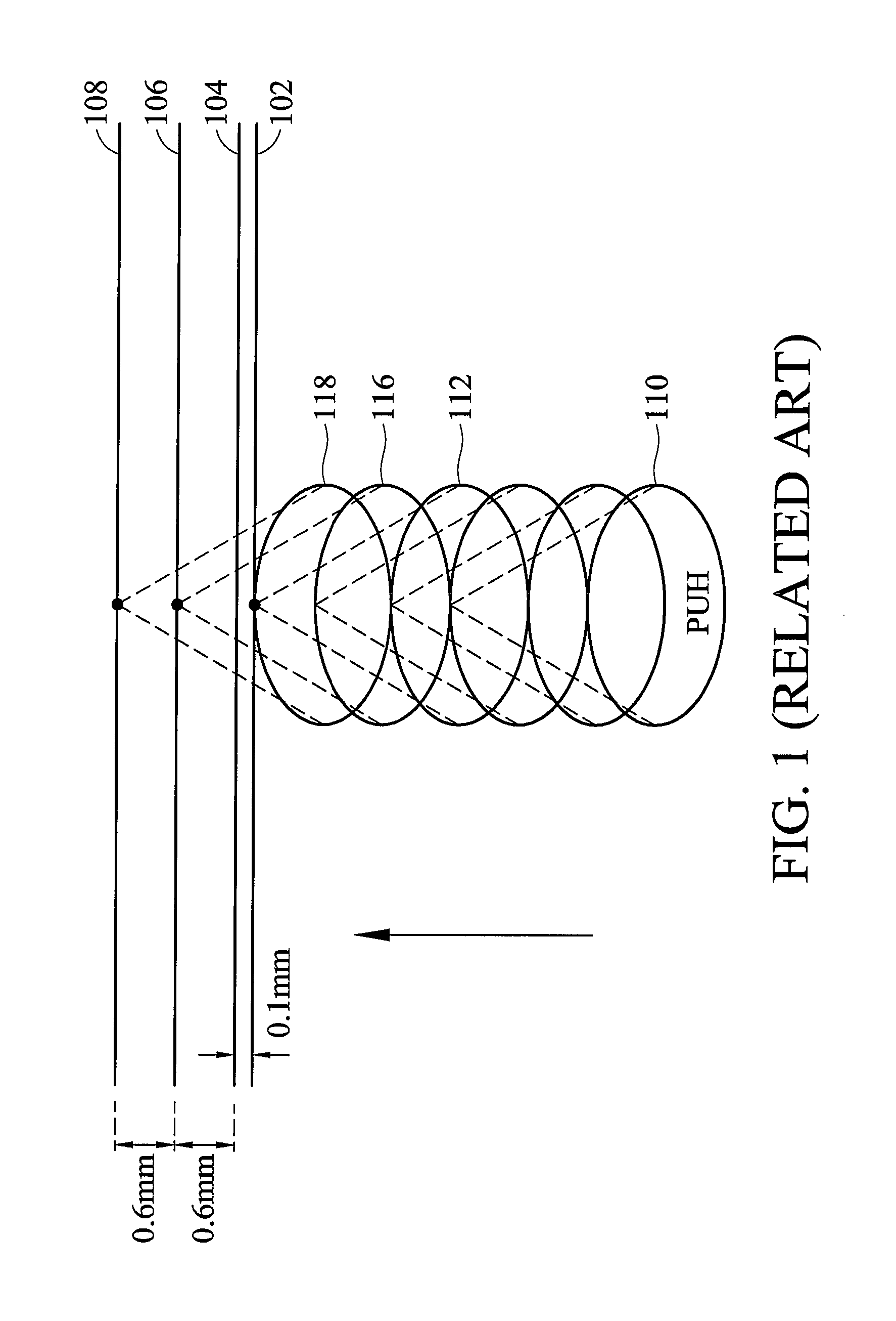
[0023]FIG. 3 shows a reflection signal detected by a pickup head when it moves towards an optical disk. The pickup head starts to move at time 322 with an initial position 110 of FIG. 1. When the pickup head moves to the position 112 of FIG. 1 at time 324, a first peak 302 caused by a polycarbonate layer surface 102 occurs in the power of the reflection signal. When the pickup head further moves to the position 116 of FIG. 1 at time 326, a second peak 304 caused by a DVD reflection layer surface 106 occurs in the power of the reflection signal if the optical disk is a DVD. Otherwise, if the optical disk is a CD, when the pickup head further moves to the position 118 of...


PUM


Abstract

The invention provides a method for identifying a disk type of an optical disk in an optical disk drive. First, a pickup head of the optical disk drive is moved towards the optical disk. A reflected signal is then observed as said pickup head of the optical drive is moving on the optical disk. A motion behavior is then detected from said reflected signal. A first period between motion initiation of the pickup head and a first peak occurrence of the power of the reflected signal is then determined, the first peak occurrence take places while the pickup head detects said motion behavior of said reflected signal is in accordance with a motion reflected by an polycarbonate layer of the optical disk. A second period between the first peak occurrence and a second peak occurrence of the power of the reflected signal is then determined, the second peak occurrence takes place while the pickup head detects said motion behavior of said reflected signal is in accordance with a motion reflected by an reflection layer of the optical disk. An identification threshold value is then determined according to the first period. The second period is then compared with the identification threshold value to obtain a comparison result. Finally, the disk type of the optical disk is identified according to the comparison result.

Description

CROSS REFERENCE TO RELATED APPLICATIONS[0001]This application claims the benefit of U.S. Provisional Application No. 60 / 827,890, filed Oct. 3, 2006, incorporated herein by reference.BACKGROUND OF THE INVENTION[0002]1. Field of the Invention[0003]The invention relates to optical disks, and more particularly to disk type identification.[0004]2. Description of the Related Art[0005]When an optical disk is inserted into an optical disk drive, the optical disk drive first has to identify the disk type, after which data of the optical disk can be retrieved accordingly. Different disk types have different distances between polycarbonate layers and reflection layers thereof. A reflection layer forms a reflection surface reflecting a radio frequency signal emitted by a pickup head of an optical disk drive, thus data stored as pits and lands on the reflection surface is read by the pickup head. A polycarbonate layer forms a transparent layer laying over the reflection layer for protection. For...

Claims


Application Information

Patent Timeline
IPC IPC(8): G11B20/18
CPCG11B20/10G11B19/12G11B2020/10879G11B2220/2545G11B2220/2562
Inventor CHANG, CHENG-HSIENCHING, YA-HSIN
Owner MEDIATEK INC
Why Eureka
Try Eureka