Retractable lens barrel unit

a barrel unit and lens technology, applied in the field of lens barrel units, can solve problems such as inability to move the lens, and achieve the effect of small configuration and stable movement of the lens uni

Inactive Publication Date: 2012-07-10
CANON KK
View PDF6 Cites 15 Cited by
  • Summary
  • Abstract
  • Description
  • Claims
  • Application Information

AI Technical Summary

Benefits of technology

[0006]The present invention provides a lens barrel unit that can maintain a stable movement of the lens unit and a small configuration.

Problems solved by technology

However, the lens barrel unit disclosed in JP 2004-085934 causes an unstable movement of the lens, since one cam follower escapes from the cam groove at the image pickup time.

Method used


Image

  • Retractable lens barrel unit
  • Retractable lens barrel unit
  • Retractable lens barrel unit

Examples


Embodiment Construction

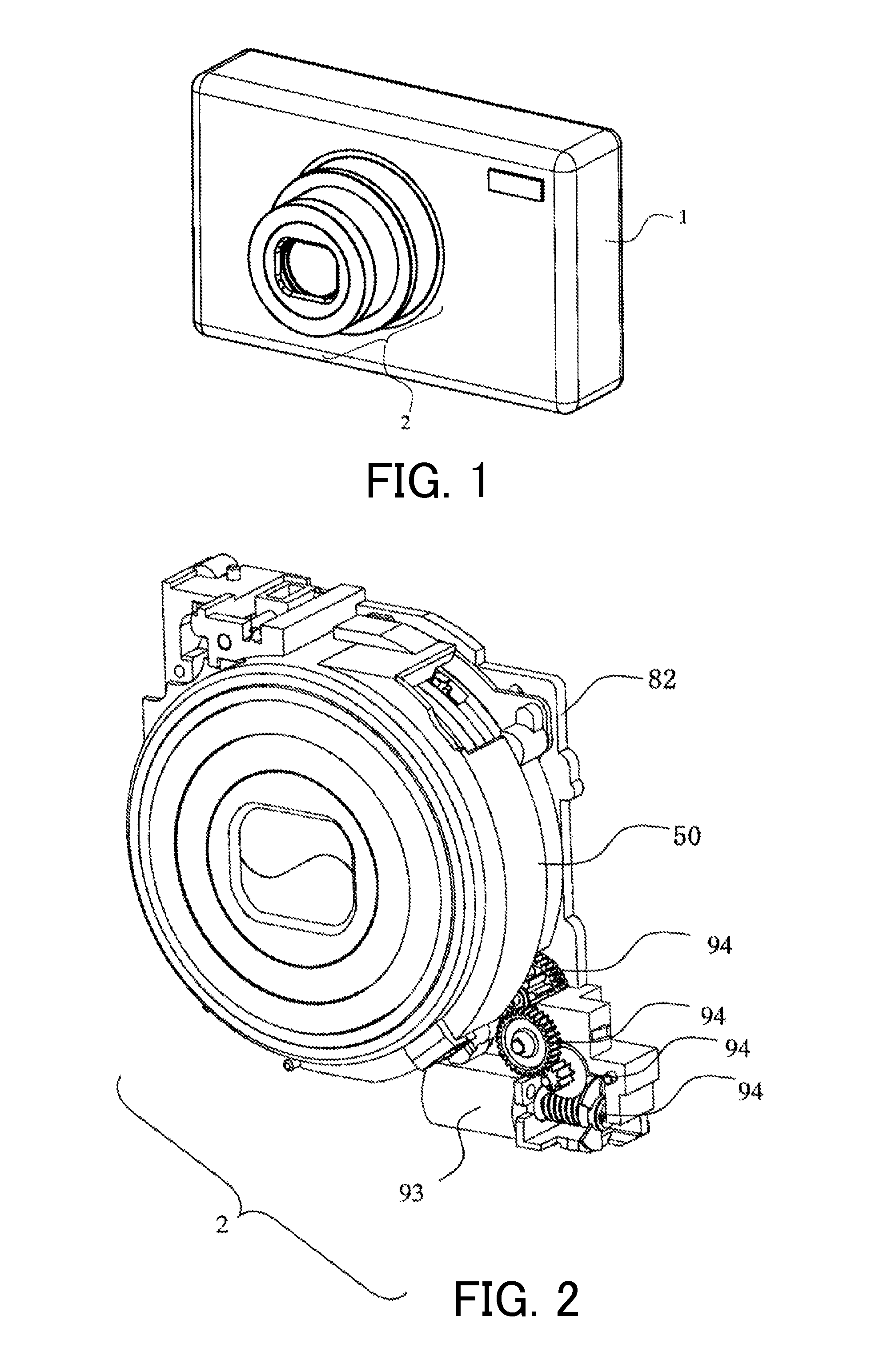
[0018]FIG. 1 is a perspective view of an image pickup apparatus (digital camera) 1 of this embodiment. As illustrated in FIG. 1, the camera 1 includes a camera body 1 and a lens barrel unit 2. The lens barrel unit 2 is a retractable barrel configured to project from the camera body 1 at an image pickup time and to retract into the camera body 1 at a non-image pickup time.

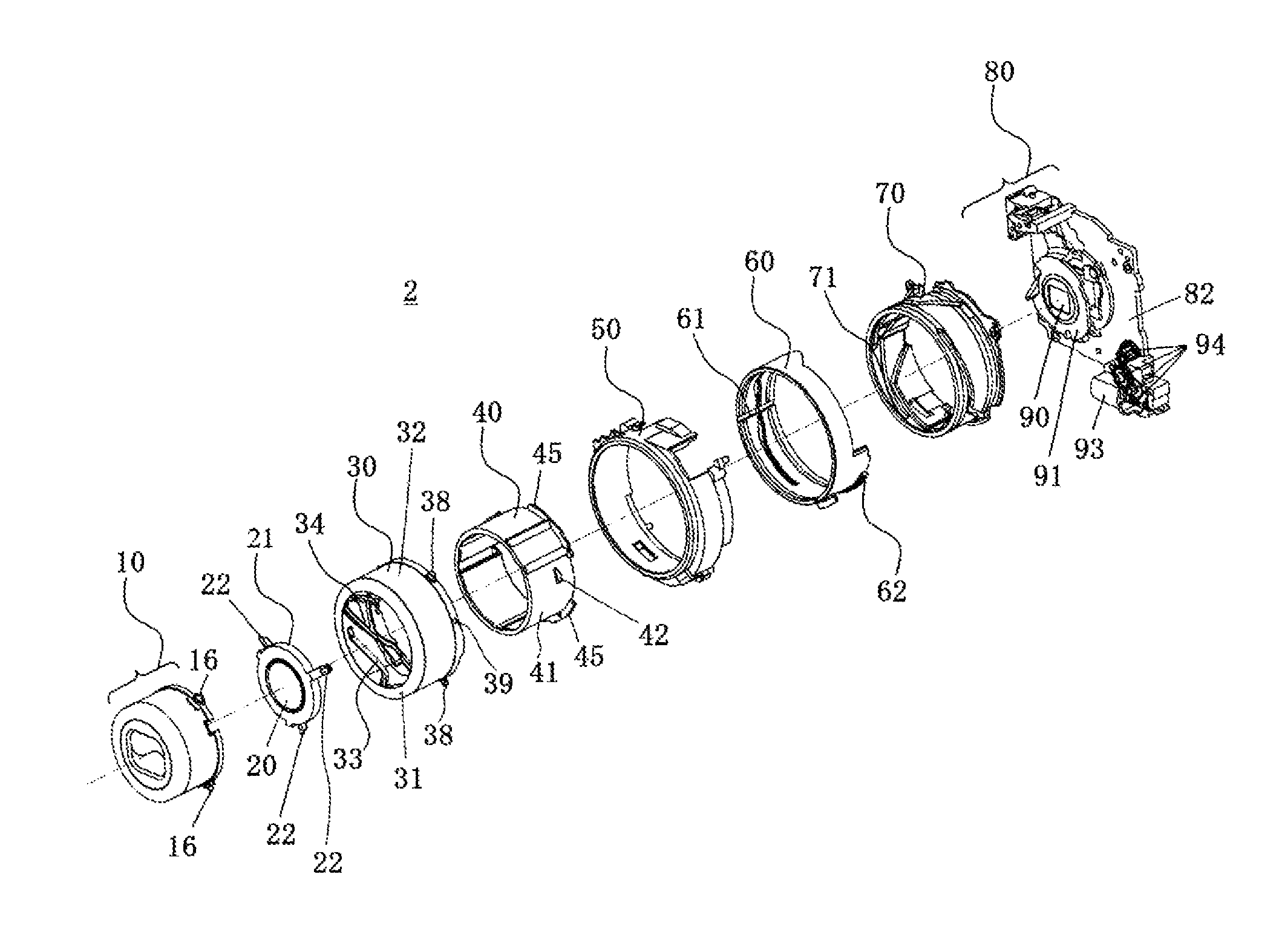
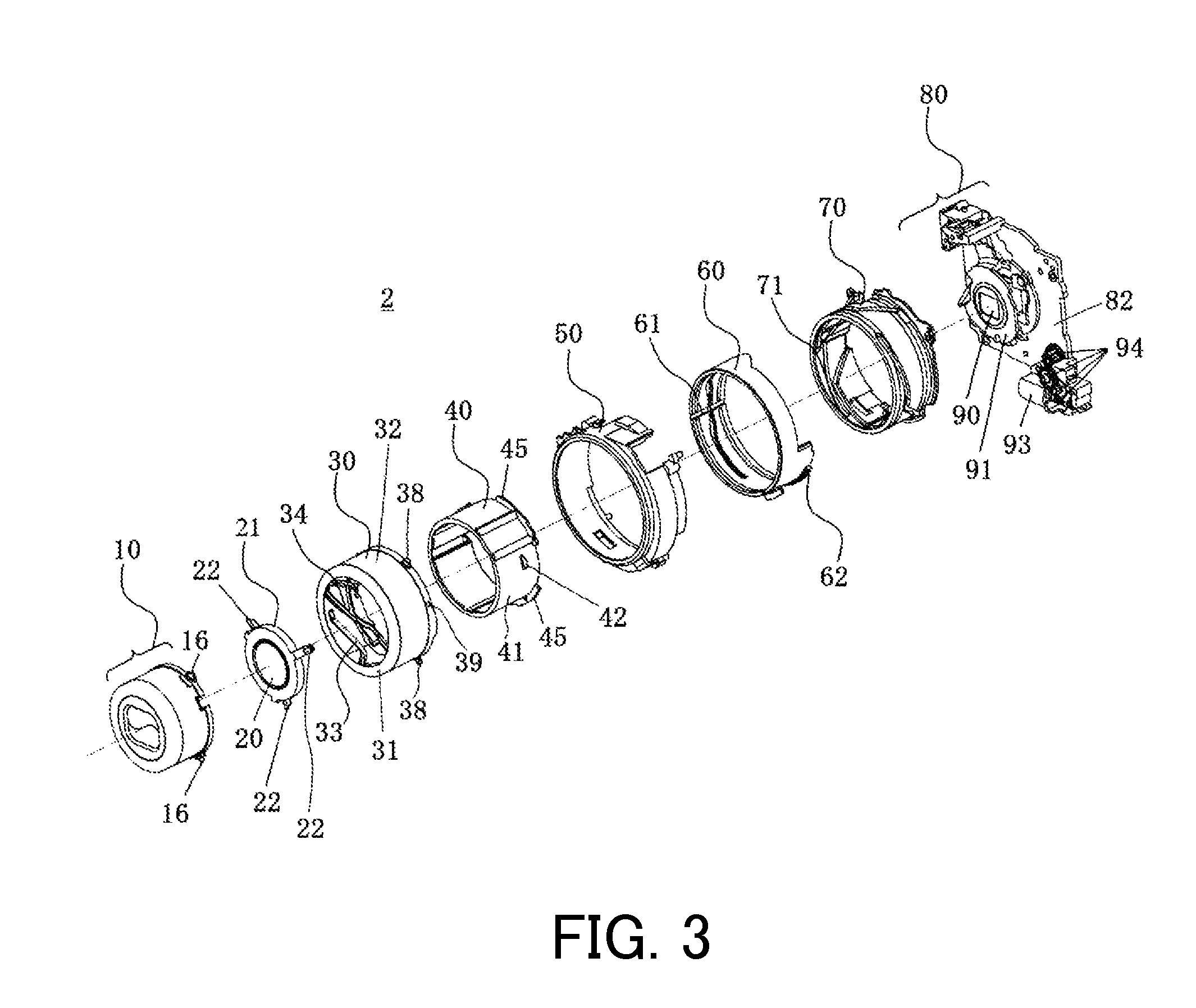
[0019]FIG. 2 is a perspective view of the lens barrel unit 2. FIG. 3 is an exploded perspective view of the lens barrel unit2. FIG. 4 is a sectional view of the lens barrel unit 2 at the image pickup state. FIG. 5 is a sectional view of the lens barrel unit 2 at the retraction state.

[0020]The lens barrel unit 2 is of a two-step retractable type including a first cylinder unit 10, a second cylinder unit, and a third cylinder unit, and can change its length in the optical axis direction illustrated by an alternate long and short dash line in FIGS. 3-5 between the image pickup time and the retraction time. The lens bar...


PUM


Abstract

A lens barrel unit includes a holder configured to hold a lens, a cam cylinder including a cam groove configured to engage with the holder and define a movement of the holder in an optical axis direction, and a projection that has a part of the cam groove and projects in the optical axis direction, and a straightforward movement cylinder configured to guide a straightforward movement of the holder, the straightforward movement cylinder including a flange forming a notch. In a process from a retraction state in which the projection is located in the notch to an image pickup state in which the projection is located outside of the notch, the straightforward movement cylinder moves relative to the cam cylinder in the optical axis direction.

Description

BACKGROUND OF THE INVENTION[0001]1. Field of the Invention[0002]The present invention relates to a lens barrel unit.[0003]2. Description of the Related Art[0004]Japanese Patent Laid-Open No. (“JP”) 2004-085934 discloses in its embodiment a lens barrel including a cam cylinder having a pair of cam grooves, and a straightforward movement cylinder having a pair of cam followers, wherein the pair of cam grooves are crossed. In this lens barrel, each cam follower is engaged with the corresponding cam groove at the retraction time, but the rear cam follower is engaged with the forward cam groove and the forward cam follower escapes from the cam groove at the image pickup time. Thus, this lens barrel unit can set a movement amount of a lens unit guided by the cam follower to a value larger than a length of the cam cylinder in an optical axis direction.[0005]However, the lens barrel unit disclosed in JP 2004-085934 causes an unstable movement of the lens, since one cam follower escapes from...

Claims


Application Information

Patent Timeline
Patent Type & Authority Patents(United States)
IPC IPC(8): G02B7/02
CPCG02B7/08
Inventor KATANO, KENICHI
Owner CANON KK
Why Eureka
Try Eureka