Apparatus for extracting the contents from a refill pouch

a technology for extracting the contents and pouches, which is applied in the direction of single-unit apparatuses, liquid transferring devices, pliable tubular containers, etc., can solve the problems of difficult to fully extract the contents from the pouches, difficult to discharge the contents from the outlet side, and contaminated or degraded initial fragrance of the contents, etc., so as to achieve easy extraction, dissipate fragrance, and avoid spillage or denaturation.

Inactive Publication Date: 2012-07-17
SANKI CO LTD
View PDF17 Cites 11 Cited by
  • Summary
  • Abstract
  • Description
  • Claims
  • Application Information

AI Technical Summary

Benefits of technology

[0008]It is an object of the present invention to provide an apparatus for extracting the contents from a refill pouch, in which the contents can be extracted by utilizing an extraction port normally formed on the pouch, whereby the contents can be completely and securely extracted without denaturing the contents or spilling the contents.
[0009]It is another object of the present invention to provide an apparatus for extracting the contents from a refill pouch, wherein the apparatus is durable in construction and reliable in operation.
[0015]The apparatus of the present invention is constructed as mentioned above and comprises a holding member for holding a refill pouch with its extraction port located downward, and a pump attached to the extraction port of the pouch. In one embodiment, the pump has a pump body that defines a substantially cylindrical housing space, and at both ends of the pump body, spindles are slidably disposed so as to be movable towards one another in the axial direction of the pump body to pressurize the housing space. In another embodiment, the wall portion of the pump body is formed of resiliently compressible, restorable and flexible material, by which the pump body can be manually squeezed to pressurize the housing space. In both embodiments, the pouch contents can be extracted through a nozzle by pressurizing the housing space sidewise from both sides. Accordingly, the extraction port usually formed on the conventional pouches can be utilized as is without cutting the bottom of the pouch, and there is no risk of spilling or denaturation of the contents, or dissipation of fragrance. Further, by grasping the spindles on both sides of the pump to move them closer to each other, or by grasping the pump wall portion made of flexible material, the pouch contents can easily be extracted, and the contents in the pouch can be completely extracted by vacuum suction. Further, the load applied to the pump at the time of operation is not directly placed on the holding member and there is no risk of falling of the pouch.
[0016]Further, one of the spindles is provided with a slanted face at its front end portion so that when the two spindles are moved towards one another to close the inlet-side valve, the slanted face presses the ball in close contact with the inlet opening, and therefore when the spindles are operated, the ball is directly moved to immediately shut the inlet opening so that the contents will not return to the inside of the pouch. Accordingly, the outlet-side valve at the outlet opening can be securely opened and the contents can be immediately extracted. If the pump wall portion is made of a resilient, flexible material, the outlet-side valve can easily be opened only by grasping and squeezing the pump body, and therefore the contents can easily be extracted. Further, if a knob is provided on an axial valve stem of a valve element that is in close contact with a valve seat of the outlet-side valve, even when the pouch contents, such as shampoo liquid, solidify within the outlet-side valve to clog the valve, the contents can be dislodged and removed by pulling the knob and forcedly opening the valve.
[0017]As mentioned above, as the usual extraction port provided on the pouch, a discharge tap to which a cap is threadedly attached, and a protruded spout having a cutting line at which the spout can be cut and removed, have been known. In the case of using the cap, a joint cap having a similar thread portion may be provided at the pump body and the pump can be threadedly connected to the discharge tap using the joint cap. In the case of using the protruded spout, an insertion-securing device may be inserted into the cutaway spout, and a screw cap having a thread portion can be threadedly fixed to the insertion-securing device and then the pump can be threadedly connected to the screw cap, thereby eliminating risk of leakage of the pouch contents. When a closing member having elasticity and an engaging section made of a metal material are provided on the insertion cylinder of the insertion-securing device, and the pouch body is attached under pressure by a clamp section, even a relatively heavy pouch for shampoo liquid, etc. can be securely held without falling, and leakage can be certainly prevented.

Problems solved by technology

Using such apparatuses, it is difficult to completely extract the shampoo liquid, etc. from the pouch.
In addition, if the container falls or the supporting member becomes detached from the wall by the pressing force, there is a likelihood that the contents may spill out from the extraction port, or air or water may enter the package through the extraction port and denature the contents, or the initial fragrance of the contents may become contaminated or degraded.
However, the apparatus of this type also has similar drawbacks since the pressing force for discharging the contents is borne by a wall surface, etc. when the button of the pump is pushed down and when the bottom of the pouch is cut and a pump is attached thereto.
However, since the housing space is small and the force pressurizing the contents is weak, there are drawbacks that when the contents are extracted, the valve at the inlet side cannot completely be closed, and due to a time difference until the valve is closed, the contents may return into the pouch through the inlet, whereby it is difficult to sufficiently discharge the contents from the outlet side.
Further, if not used for a long period of time, the contents, such as shampoo liquid, may solidify at the valve portion on the outlet side and clog the outlet opening.

Method used


Image

  • Apparatus for extracting the contents from a refill pouch
  • Apparatus for extracting the contents from a refill pouch
  • Apparatus for extracting the contents from a refill pouch

Examples


Embodiment Construction

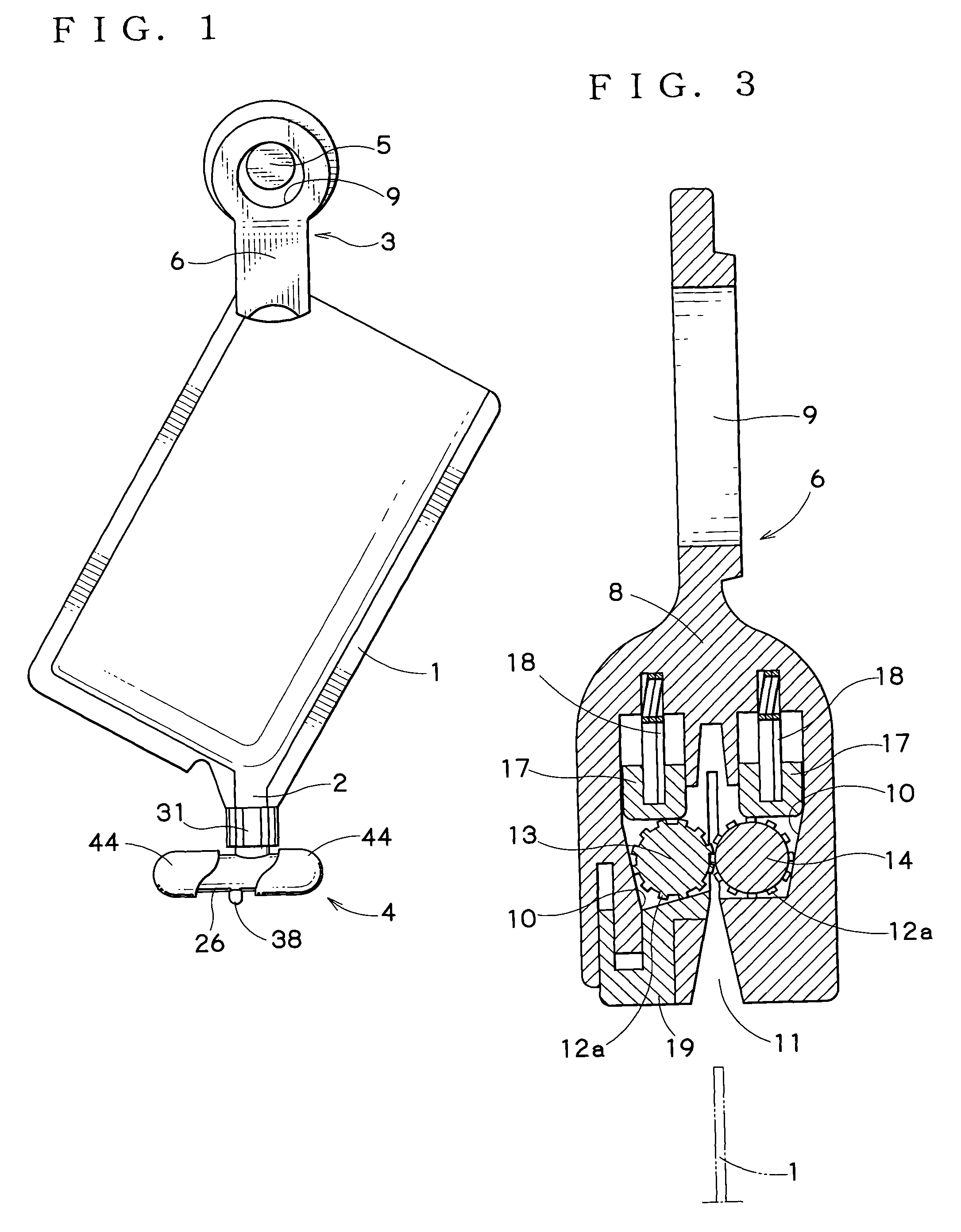
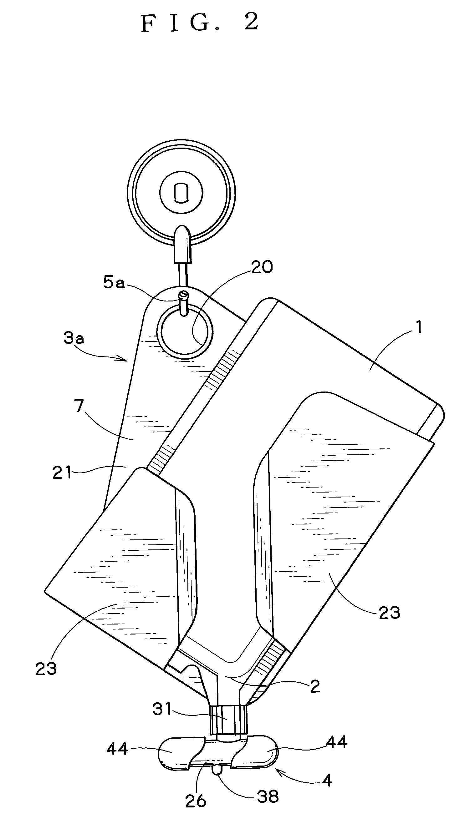
[0039]FIGS. 1 and 2 show two embodiments of the present invention, and in each embodiment the apparatus comprises a holding member 3 (FIG. 1) or 3a (FIG. 2) for holding a refill pouch 1 with its extraction port (discharge tap) 2 directed downward, and a pump 4 attachable to the extraction port 2 of the pouch 1. In these embodiments, the refill pouch is of the type having a screw cap (not shown) that is threadedly attached to the extraction port so that when the cap is removed, the pump 4 can be threadedly attached to the extraction port 2.

[0040]In the embodiment shown in FIG. 1, the holding member 3 comprises a gripping device 6 for releasably gripping the bottom of the pouch 1 (the upper portion in the drawing) and by which the pouch can be hung on a hook 5 or the like fixed to a wall by a suction cup, etc., so that the pouch hangs upside down. In the embodiment shown in FIG. 2, the holding member 3a comprises a housing case 7 for holding the pouch 1 therein in an upside down state...


PUM

PropertyMeasurementUnit
flexibleaaaaaaaaaa
fluidityaaaaaaaaaa
pressing forceaaaaaaaaaa

Abstract

An apparatus for extracting the contents from a refill pouch comprises a holding member for holding the pouch with its extraction port facing downward, and a pump attached to the extraction port of the pouch. The pump has a pump body defining a housing space having an inlet opening and an outlet opening, an inlet-side valve which communicates with the extraction port to open and close the inlet opening so that the contents can be introduced into the housing space from the pouch, and an outlet-side valve to open and close the outlet opening so that the contents in the housing space can be discharged through a nozzle that communicates with the outlet-side valve. The pump wall portion is constituted by a resiliently compressible, restorable and flexible material so that the contents in the housing space can be extracted through the nozzle by manually squeezing the pump wall portion thereby pressurizing the housing space.

Description

BACKGROUND OF THE INVENTION[0001](1) Field of the Invention[0002]The present invention relates to an apparatus for extracting the contents from a refill pouch, and more particularly to an apparatus by which pouch contents having fluidity, such as shampoo liquid, can easily be extracted from refill pouches, such as a shampoo liquid package, a rinse package, a detergent package and the like for refilling a dispenser or other container.[0003](2) Description of the Related Art[0004]Refill pouches, such as a shampoo liquid package for refilling a container, are typically provided with either an extraction port having a tearable spout or a discharge tap stopped with a screw cap. Usually, after opening the extraction port, the contents in the package are dispensed to a container, for example, a shampoo container, for later use.[0005]JP-A-2000-142851 describes an apparatus by which the contents can be directly extracted from a refill package and used without dispensing them to, for example,...

Claims


Application Information

Patent Timeline
Patent Type & Authority Patents(United States)
IPC IPC(8): B67D7/06B67D7/58
CPCA47K5/1204B05B11/3015B05B11/3032B05B11/3045B65D75/56B05B11/0043B05B11/1015B05B11/026B05B11/1032B05B11/1045B65D31/14B65D33/00
Inventor ABE, MASAYUKI
Owner SANKI CO LTD
Why Eureka
Try Eureka