Anchor rod anchor system of a concrete wall form

a technology of anchor system and concrete wall, which is applied in the direction of form/shuttering/falseworks, shaping building parts, constructions, etc., can solve the problems of heavy load on the locking device, the difficulty of engaging the thread of the locking device on the rear of the second form element,

Active Publication Date: 2012-07-17
PERI GMBH +1
View PDF28 Cites 16 Cited by
  • Summary
  • Abstract
  • Description
  • Claims
  • Application Information

AI Technical Summary

Benefits of technology

[0020]If a locking device with a tubular guidance facility and/or an anti-rotation lock is used as the second locking device, finding the screw thread of the second locking device is easier and/or the second locking device does not have to be held secure by a formwork erector to prevent the anchor rod from rotating during screwing.
[0021]In an inventive concrete wall form, an anchor system is very advantageously used, in which a first screw thread in the end region of the anchor rod facing away from the anchor rod tip has a larger thread diameter than a second screw thread in the end region of the anchor rod near to the anchor rod tip, preferably with an anchor rod that conically tapers. If the second screw thread of the anchor rod of the anchor system is screwed completely into the screw nut element of the second locking device of the anch

Problems solved by technology

With the known anchor systems, there are problems with inserting the anchor rod when the concrete wall form is erected, if the anchor insertion holes of the form elements with their formwork shells facing each other and forming the concrete wall are not sufficiently well-aligned opposite each other.
The latter anchor insertion hole is found relatively easily but, with poorly aligned anchor insertion holes, the anchor rod extends obliquely with respect to the formwor

Method used


Image

  • Anchor rod anchor system of a concrete wall form
  • Anchor rod anchor system of a concrete wall form
  • Anchor rod anchor system of a concrete wall form

Examples


Embodiment Construction

[0025]The figures of the drawings show the inventive object highly schematically and are not scale drawings. The individual parts of the inventive object are shown in such a way that their structure is clearly visible.

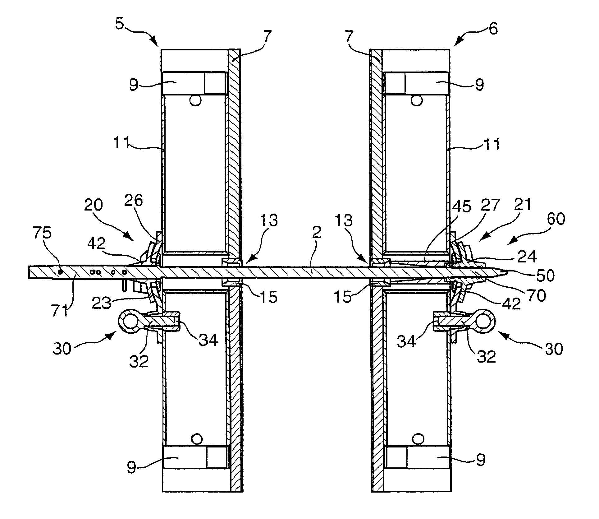
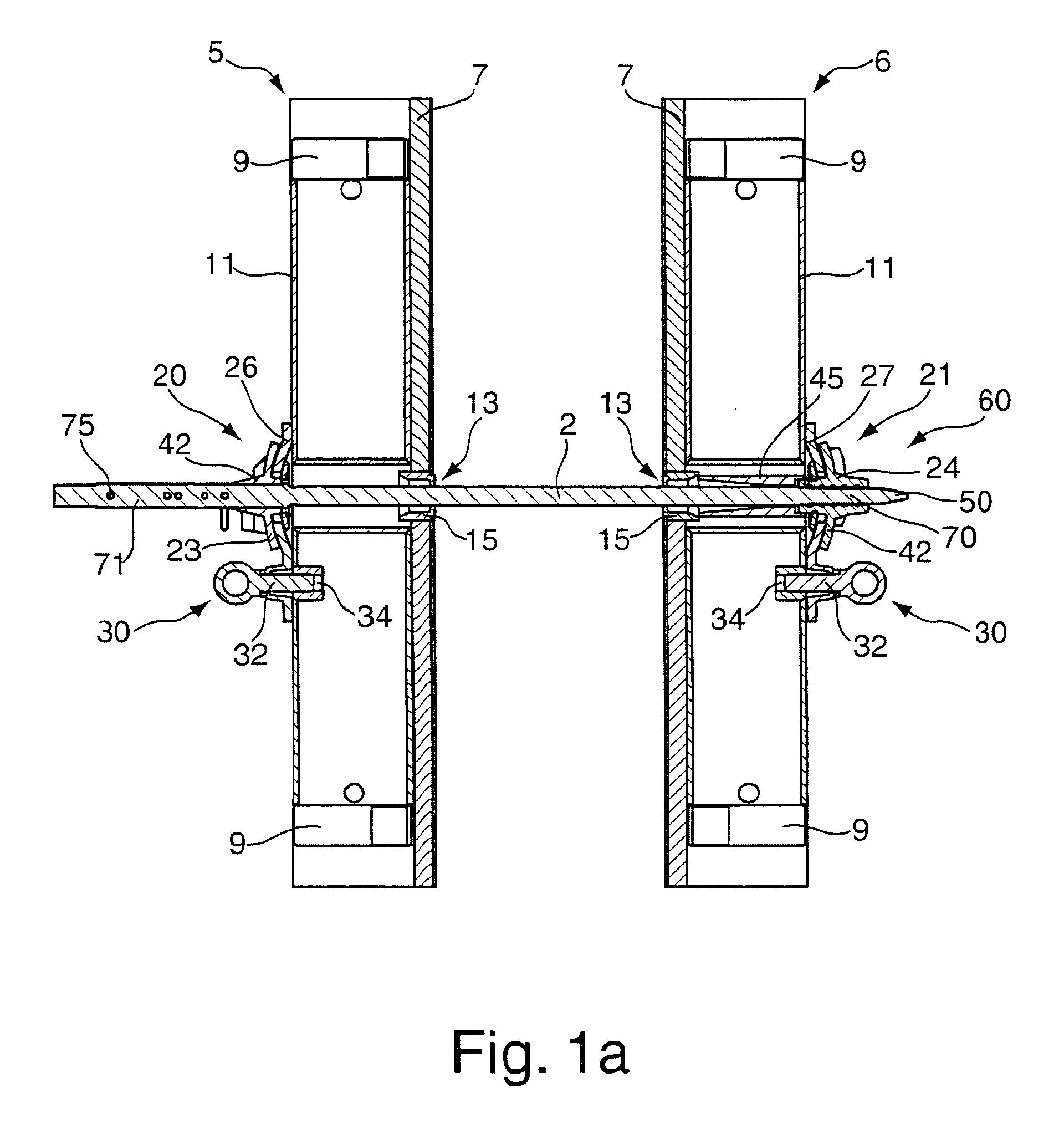
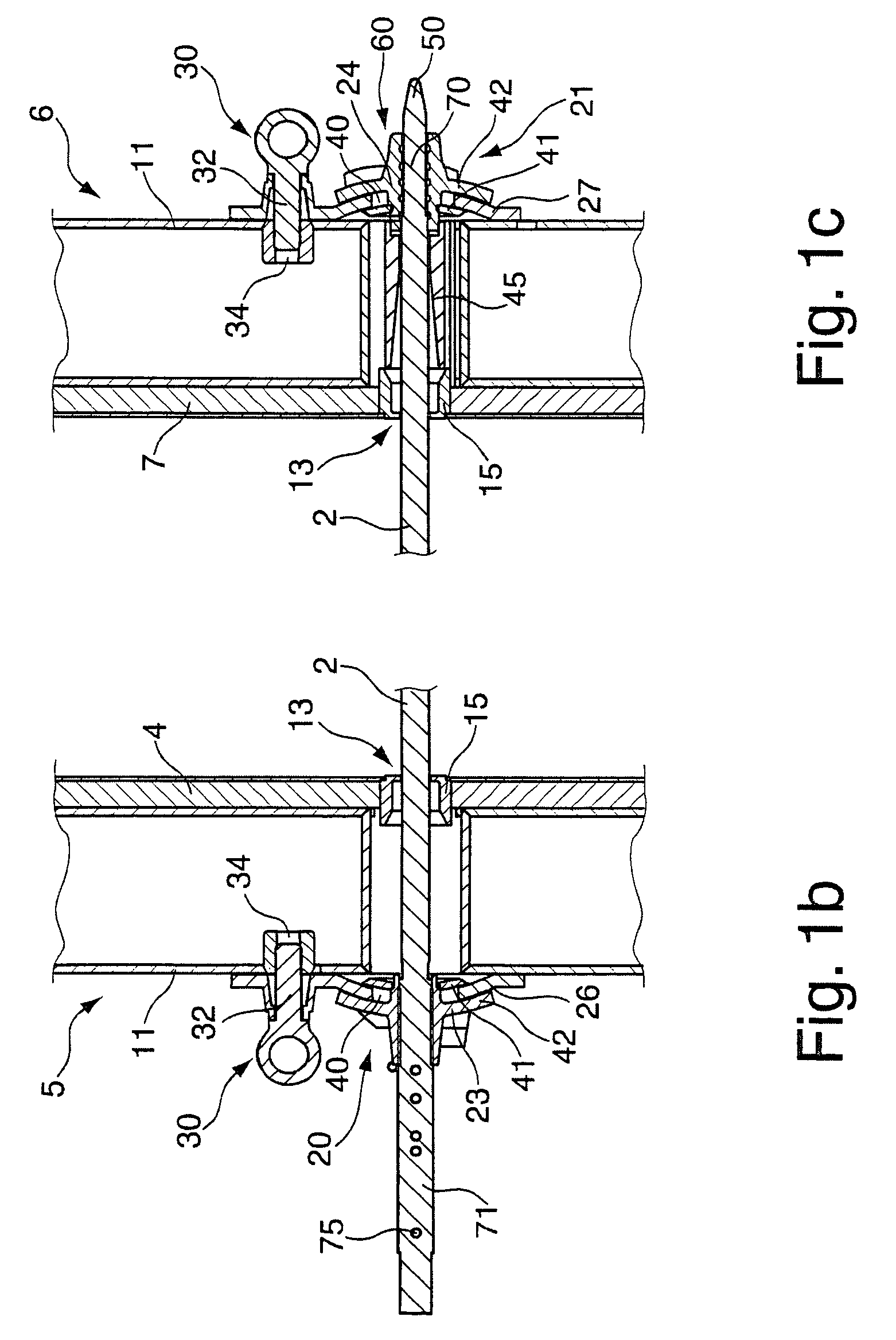
[0026]FIGS. 1 to 4 each show an embodiment of an inventive concrete wall form in various phases of implementation of an anchor rod 2 of an inventive anchor system in a section through the relevant inventive anchor system. Each figure shows a first and a second form element 5,6. The form elements 5,6 each have a formwork shell 7 and longitudinal and tie beams 9, onto which the formwork shell 7 is usually riveted. In each case, the sectional representation extends through a longitudinal beam so that each longitudinal beam is only represented by the wall 11 of the steel section from which the beam is made. The formwork shells 7 of the form elements 5,6 are located opposite each other to form a wall to be cast in concrete. One anchor insertion hole 13 is provided in the fo...


PUM


Abstract

A locking device (20,21) for an anchor rod (2) of an anchor system of a concrete wall form, has a screw nut element for screwing the anchor rod through a screw thread of the screw nut element. A dome plate can be fastened to a back of a form element (5,6) of the concrete wall form by means of fastening elements (30) and has a spherically shaped plate section with an opening in which the screw nut element is arranged so as to have radial play. The screw nut element has a groove-type radial seat which accommodates the edges of the opening in the spherical plate sections.

Description

[0001]This application is the national stage of PCT / DE2008 / 00016 filed on Jan. 23, 2008 and also claims Paris Convention priority to DE 10 2007 004 226.6 filed on Jan. 27, 2007.BACKGROUND OF THE INVENTION[0002]The invention relates to an anchor system of a concrete wall form with at least one locking device for an anchor rod of the anchor system, wherein the locking device has a screw nut element for screwing the anchor rod through a screw thread of the screw nut element.[0003]Such anchor systems are used in formwork for steel-reinforced concrete structures. Concrete wall forms are made up of a formwork shell and its supporting elements, for example, longitudinal girders and tie beams. The two sides of a wall are each formed from one concrete form element, that is, a half-form, which are held together by anchor rods. The anchor rods are inserted through holes in the formwork shell and fixed at their ends to the elements supporting the formwork shell in such a way that the tensile fo...

Claims


Application Information

Patent Timeline
IPC IPC(8): E04G17/065E04G11/08
CPCE04G17/0657
Inventor SCHWOERER, ARTUR
Owner PERI GMBH
Why Eureka
Try Eureka