System for tracking a moving object, by using particle filtering

a technology for moving objects and systems, applied in television systems, instruments, lighting and heating apparatuses, etc., can solve the problems of inability to detect objects, disadvantageous tracking methods, and decreased tracking ability in that region, and achieve the effect of increasing the ability to track moving objects

Inactive Publication Date: 2012-07-17
KK TOSHIBA
View PDF10 Cites 12 Cited by
  • Summary
  • Abstract
  • Description
  • Claims
  • Application Information

AI Technical Summary

Benefits of technology

[0014]An object of the present invention is to provide a tracking system for performing a tracking method that uses particle filtering, which can reliably arrange particles with respect to a moving object, irrespective of the ability of detecting the moving object in the initialization process, and which can therefore increase the ability of tracking the moving object.

Problems solved by technology

Even if the motion model is used, however, the ability of tracking that region may decrease if the candidate region changes in shape, from time to time, due to the moving object as seen (at a specific camera view angle) or to the ability of detecting that region.
The tracking method is disadvantageous, however, in the following respects.
In this case, however, the object can hardly be detected if the background is complicated and many other objects exist.
Further, any other moving object cannot be well tracked based on the initial value acquired of the first moving objected detected if the initial value is not so accurate as desired.
Inevitably, the system model may be located at a wrong position if the background is found to have high likelihood in the likelihood inference process.

Method used


Image

  • System for tracking a moving object, by using particle filtering
  • System for tracking a moving object, by using particle filtering
  • System for tracking a moving object, by using particle filtering

Examples


first embodiment

(Configuration of the System)

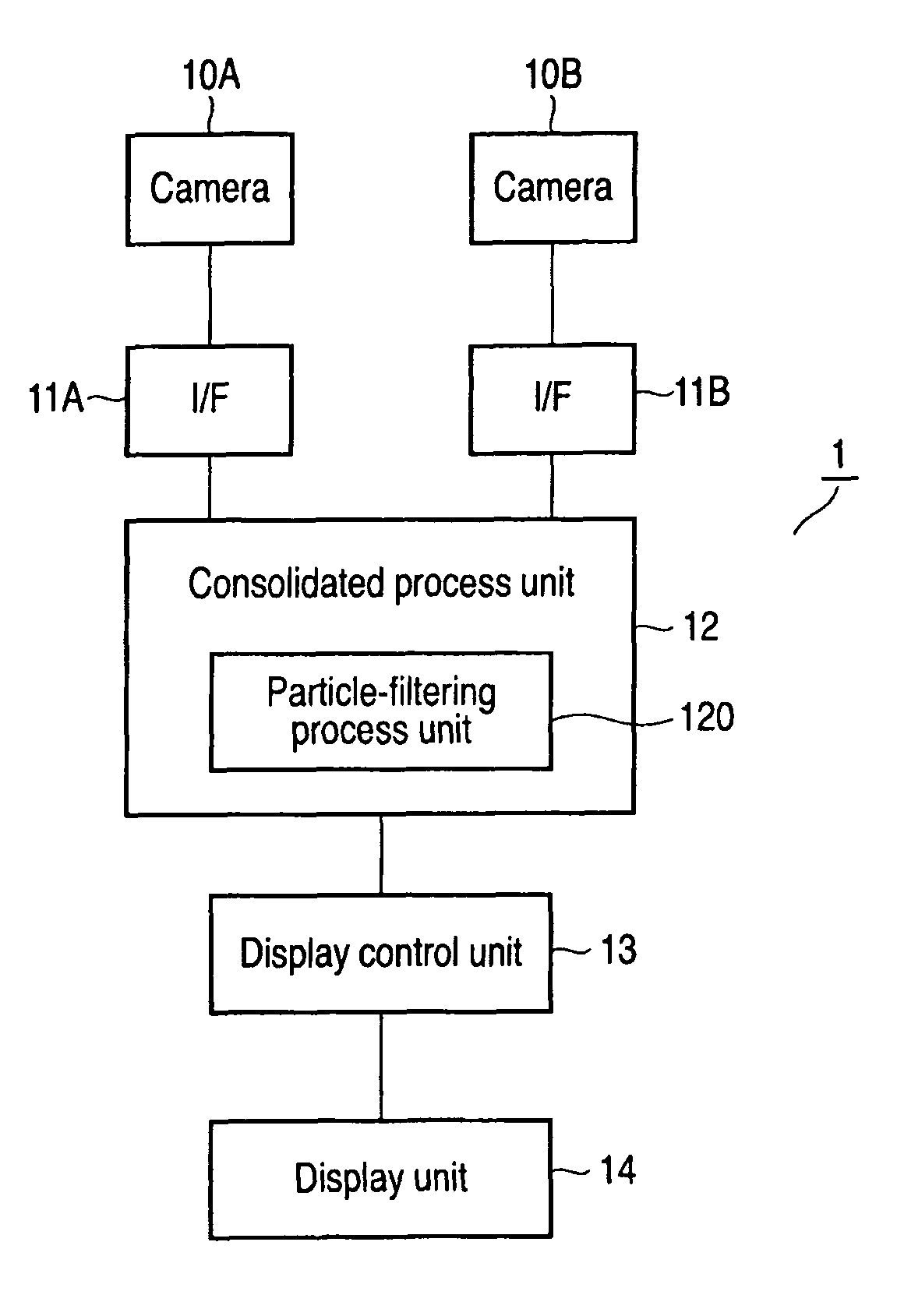
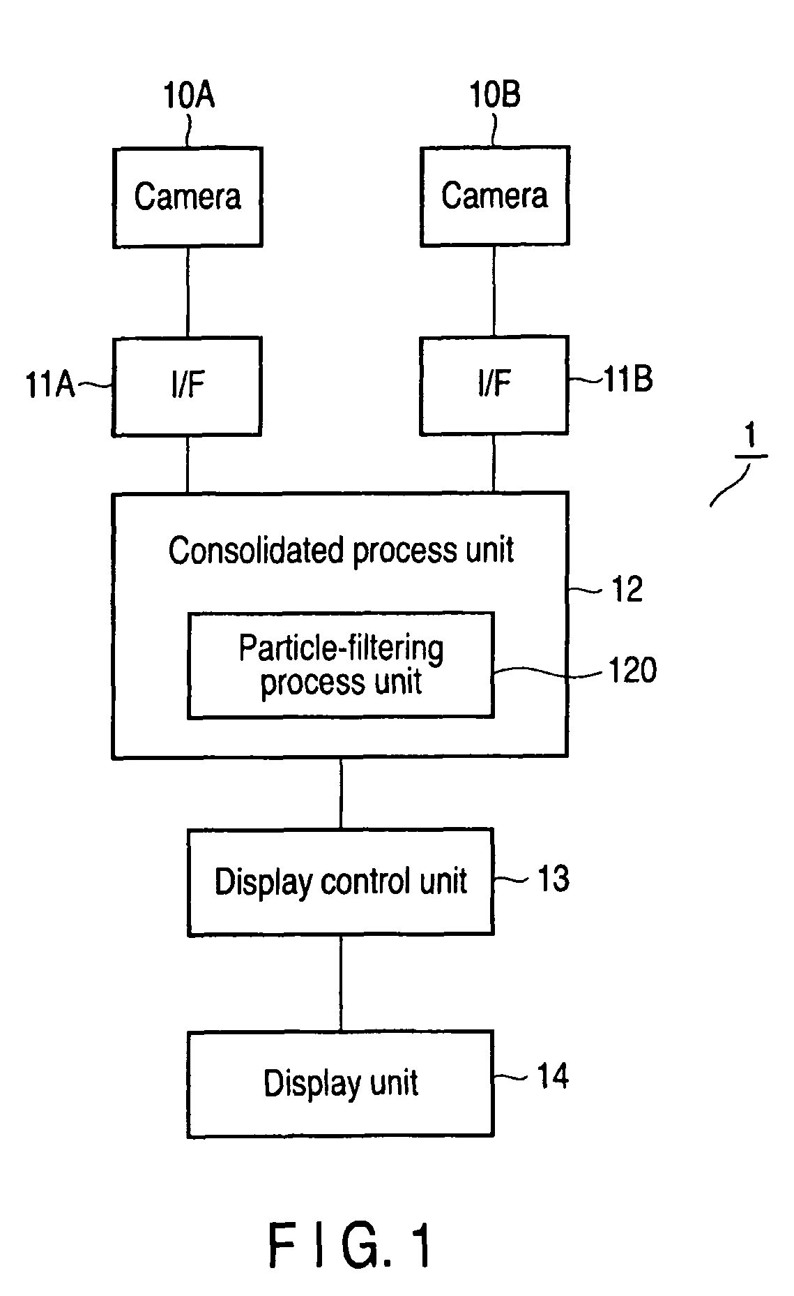
[0033]FIG. 1 is a block diagram showing the major components of a tracking system 1 according to a first embodiment.

[0034]As FIG. 1 shows, the tracking system 1 has first and second cameras 10A and 10B, interfaces 11A and 11B, a consolidated process unit 12, a display control unit 13, and a display unit 14. The interfaces 11A and 11B are connected to the cameras 10A and 10B, respectively.

[0035]The first and second cameras 10A and 10B are installed in, for example, a building. They are video cameras for photographing moving objects, such as men walking in the building. The interface 11A processes the video data acquired by the camera 10A, generating a digital video signal. Similarly, the interface 11B processes the video data acquired by the camera 10B, generating a digital video signal. The digital video signals are supplied to the consolidated process unit 12.

[0036]The consolidated process unit 12 is a main unit of the tracking system 1. The unit 12 is ...

second embodiment

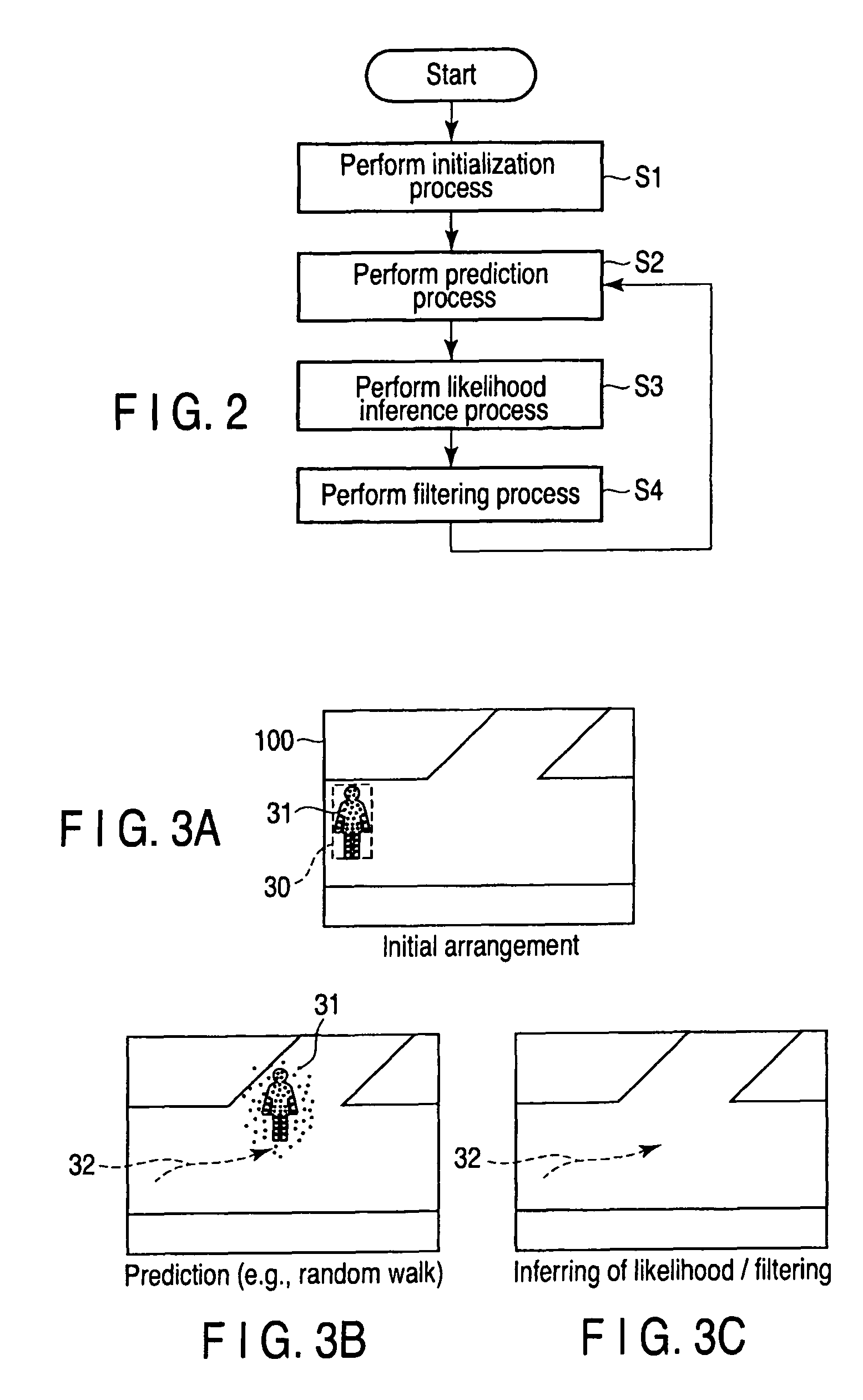
[0054]FIGS. 6A to 6C, 7A to 7C, and 8 are a diagram explaining the operation of a particle filter 120 according to a second embodiment of this invention. This particle filter 120 is incorporated in a tracking system that is identical in configuration to the tracking system 1 shown in FIG. 1. Therefore, the tracking system according to the second embodiment will not be described.

[0055]The particle filter 120 according to this embodiment has the function of cancelling occlusion that may occur while the tracking method is being performed after the initialization process (i.e., initial arranging and rearranging of particles), prediction process and likelihood inference process.

[0056]Occlusion is a phenomenon that may occur if, for example, some persons are photographed, one overlapping another. If occlusion happens, the image photographed will be shadowed, in part or entirety, and cannot be recognized. If the occlusion happens, only the person standing foremost will have high likelihood...

third embodiment

[0065]FIGS. 9 to 11 are diagrams explaining how a particle filter 120 according to a third embodiment of the invention operates. In this embodiment, too, the tracking system incorporating the particle filter 120 is identical in configuration to the tracking system 1 shown in FIG. 1. Therefore, the tracking system according to the third embodiment will not be described.

[0066]The particle filter 120 according to this embodiment has the function of controlling the likelihood value in the likelihood inference process, after the above-mentioned initialization process has been completed (that is, after the particles have been initially arranged and then rearranged) in the tracking method that is composed of the initialization process, prediction process, likelihood inference process and filtering process.

[0067]The particle filer 120 first defines the characteristic value of the moving object to track, such as a man, as a likelihood function, and then infers the likelihood each particle ar...


PUM


Abstract

In a tracking system for tracking a moving object by using a particle filter, the particle filter is configured to arrange particles initially, in a standby state, in a given background region provided in the screen of a camera and to rearrange the particles with respect to the moving object in accordance with a change in likelihood that the object has with respect to the particles.

Description

CROSS-REFERENCE TO RELATED APPLICATIONS[0001]This application is based upon and claims the benefit of priority from prior Japanese Patent Application No. 2008-040614, filed Feb. 21, 2008, the entire contents of which are incorporated herein by reference.BACKGROUND OF THE INVENTION[0002]1. Field of the Invention[0003]The present invention relates to a system for tracking a moving object, such as a man, by utilizing particle filtering.[0004]2. Description of the Related Art[0005]A system has been developed, which processes video data acquired by a camera, thereby tracking an object, such as a walking man or any other moving object. (See, for example, Jpn. Pat. Appln. KOKAI Publication No. 2003-216951.) In recent years, a system for tracking a moving object by means of an algorithm called “particle filtering” has been exploited. (See, for example, Jpn. Pat. Appln. KOKAI Publication No. 2005-165688.).[0006]In a tracking method utilizing particle filtering, particle filtering is performe...

Claims


Application Information

Patent Timeline
Patent Type & Authority Patents(United States)
IPC IPC(8): H04N5/225
CPCG06T7/208G06T7/277F24H1/181F16L15/04
Inventor BABA, KENJIENOHARA, TAKAAKISUZUKI, YOSHIHIKOTAKAHASHI, YUSUKE
Owner KK TOSHIBA
Why Eureka
Try Eureka