
Broadband antenna system allowing multiple stacked collinear devices

a collinear device and antenna system technology, applied in the field of broadband antenna systems, can solve the problems of inability to stack coupling and interference, and inability to achieve the stacking of multiple antenna elements or other devices,

Active Publication Date: 2012-07-24
FIRST RF CORP
View PDF25 Cites 25 Cited by
  • Summary
  • Abstract
  • Description
  • Claims
  • Application Information

AI Technical Summary

Problems solved by technology

Nonetheless, this antenna system was limited by the very small opening in the conic tips of the biconical dipole, which resulted in coupling and interference.
An unsolved problem has been providing the feed to the stacked biconical structures without interfering with the RF performance of the lower biconical element.
Unlike the present invention, however, the foregoing designs do not permit the stacking of multiple antenna elements or other devices, because feed lines or cables cannot be run from the hollow central elements through the feed region without causing interference.
The functionality is limited because it does not have full control over phase and amplitude weighting.
This approach also does not allow the ability to use antennas that perform at different frequency bands or perform independently of each other.
The chokes are in close proximity to the actual feed, thus reducing the radiation efficiency of the antenna system.

Method used


Image

  • Broadband antenna system allowing multiple stacked collinear devices
  • Broadband antenna system allowing multiple stacked collinear devices
  • Broadband antenna system allowing multiple stacked collinear devices

Examples


first embodiment

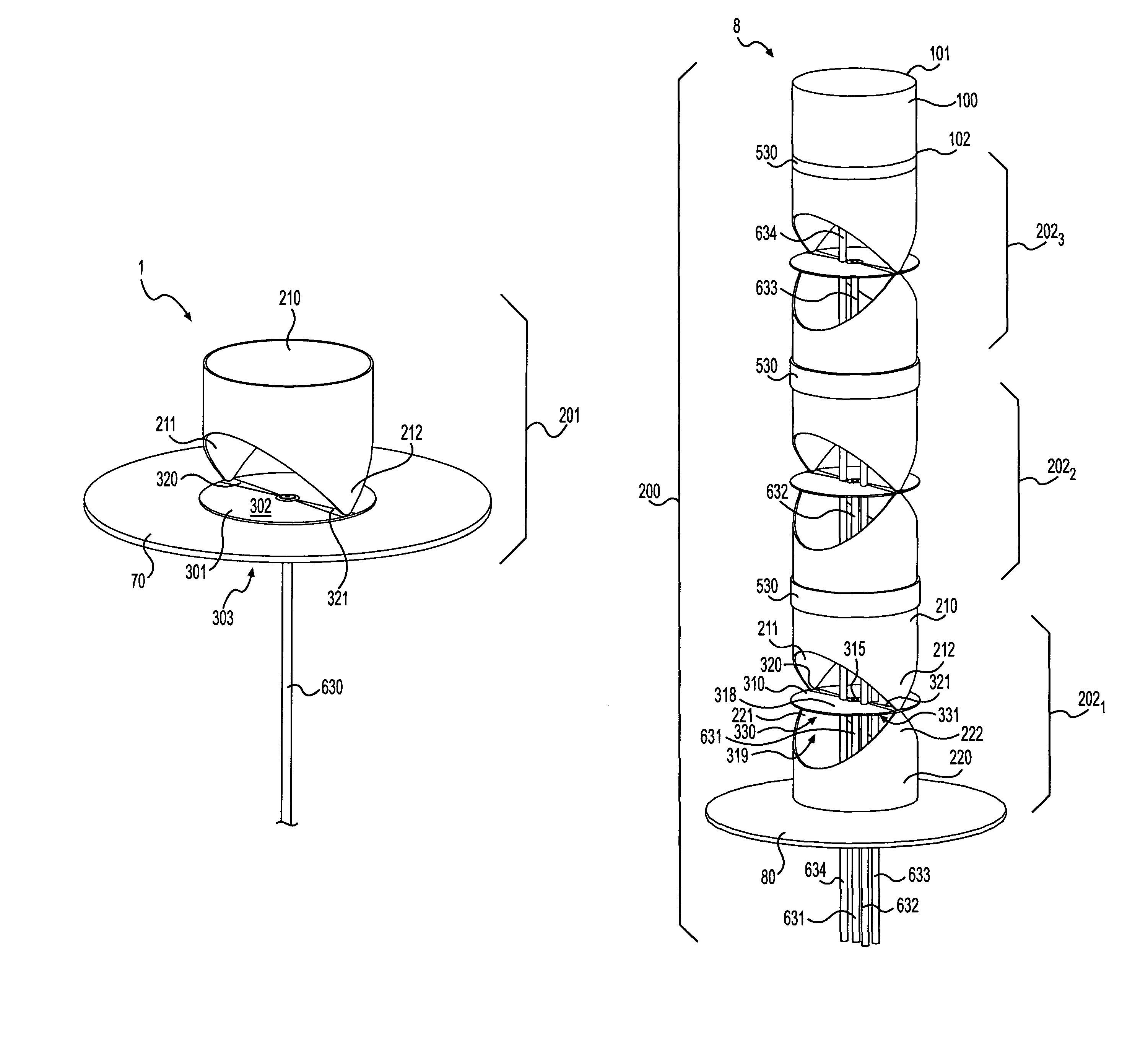
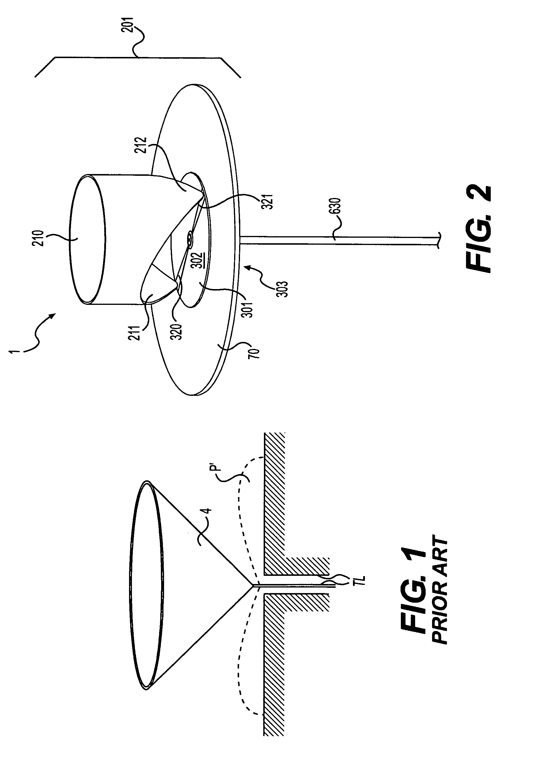
[0060]Referring to FIG. 1, a prior art monocone antenna disposed above a ground plane is shown. The prior art monocone exemplifies the conical shape, single conic tip and single feed found in the known art. In comparison, a “coneless monocone” according to the present invention is shown in FIG. 2. Coneless monocone antenna system 1 of the present invention comprises modified “coneless” radiator 210, wherein the feed portion of the cone is cut away and the cone is modified to be substantially cylindrical, leaving “tapered feed points”211 and 212 in place of the typical prior art conic tip. Although not shown, the monocone antenna system of the present invention also contemplates a design having a single tapered feed point in place of the typical prior art conic tip.

[0061]With continuing reference to FIG. 2, coneless monocone antenna system 1 of the present invention preferably comprises coneless monocone 201, having coneless radiator 210 disposed on limited ground plane 70, which fur...

second embodiment

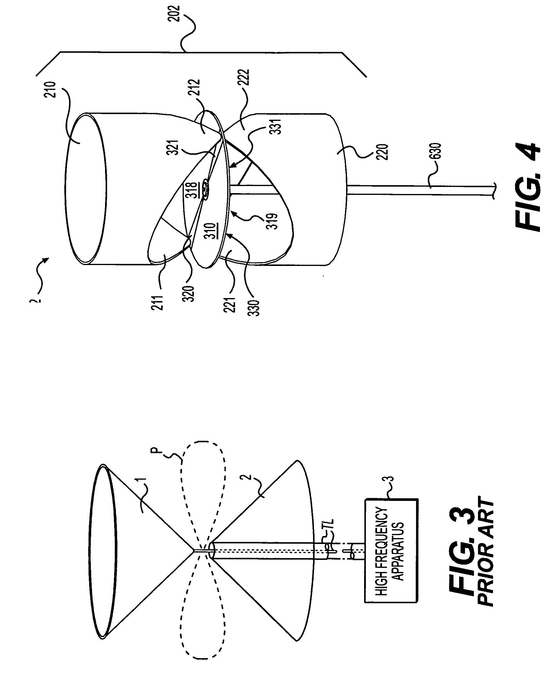
[0063]Referring now to FIG. 3, a typical prior art biconical antenna is shown, comprising two conic tips and a single feed region. In comparison in FIG. 4, a “coneless biconical” antenna according to the present invention is shown. Referring now to FIG. 4, coneless biconical antenna system 2 preferably comprises modified upper coneless radiator 210, wherein a portion of the conic region of the cone is cut away and the cone is modified to be substantially cylindrical, leaving two upper “tapered feed points”211 and 212 in place of the known upper conic tip, and modified lower coneless radiator 220, having the same shaped or cut-away portion as upper coneless radiator 210, and leaving two lower “tapered feed points”221 and 222 in place of the known lower conic tip.

[0064]With continuing reference to FIG. 4, coneless biconical antenna system 2 of the present invention preferably comprises coneless biconical 202, having upper coneless radiator 210 disposed on balun 310, which further comp...

fifth embodiment

[0068]Referring now to FIG. 7, the present invention is shown as coneless monocone antenna system 5. Coneless monocone antenna system 5 preferably comprises coneless monocone 201, having coneless radiator 210 disposed on limited ground plane 70, which further comprises microwave substrate 301. Microwave substrate 301 further comprises upper surface 302 and lower surface 303 (not visible in the perspective view). As embodied herein, coneless radiator 210 preferably is shaped to provide first tapered feed point 211, second tapered feed point 212, third tapered feed point 213, and fourth tapered feed point 214, which are electrically connected respectively with first feed side trace 320, second feed side trace 321, third feed side trace 322, and fourth feed side trace 323 on upper surface 302 of microwave substrate 301.

[0069]As embodied herein, the highest frequency of operation of the present invention may be determined by the number of feed points, the spacing between the feed points...


PUM


Abstract

A broadband antenna system is disclosed. The antenna system relates to a modified conical structure, wherein the feed region of the cone is cut away to form a hollow “coneless” cylinder, and the distribution of one or more tapered feed points around the circumference of the cylinder allows a plurality of feed lines, cables, piping, or other structures to be run through the center of the antenna without interfering with the performance of the antenna system. The invention further relates to a stacked broadband antenna system wherein additional coneless elements, as well as other types of antennas or devices, may be stacked collinearly on, or disposed coaxially to, the cylindrical antenna structure, and fed, powered or operated via the plurality of feed lines, cables, piping or other structures. The overall system may thus provide a wide range of transmitting, receiving, sensing and other capabilities. By stacking a plurality of coneless elements with other antennas, the antenna system of the present invention may provide a virtually infinite bandwidth.

Description

CROSS REFERENCE TO RELATED APPLICATIONS[0001]This application is related to and claims the benefit of prior-filed U.S. Provisional Application for Patent Ser. No. 61 / 064,725 filed on 21 Mar. 2008, entitled “MODIFIED CONICAL ANTENNA SYSTEM ALLOWING MULTIPLE STACKED COLLINEAR ELEMENTS,” which is incorporated herein by reference.FIELD OF THE INVENTION[0002]The present invention relates to a broadband antenna system, and more particularly, to a modified conical antenna structure wherein the feed region is cut away to form a substantially cylindrical shape termed herein “coneless.” The enlarged feed region and distribution of tapered feed points around the circumference of the “coneless” cylinder permit the collinear and coaxial stacking of multiple antenna elements or other devices. The additional antennas or other devices may be disposed within or stacked on the shaped antenna structure without interfering with the performance of the antenna system, thus providing a wide range of sensi...

Claims


Application Information

Patent Timeline
Patent Type & Authority Patents(United States)
IPC IPC(8): H01Q1/50H01Q21/00H01Q1/48H01Q9/28H01Q9/16
CPCH01Q9/28H01Q21/10
Inventor LALEZARI, FARZIN
Owner FIRST RF CORP
Learn More