Image forming apparatus and control method therefor

a technology of image forming apparatus and control method, which is applied in the direction of electrographic process apparatus, instruments, optics, etc., can solve the problems of excessive printing on the back side, increase a cost, and the multiplication of printing mechanisms will enlarge the apparatus, so as to avoid unnecessary switching operations and improve print productivity.

Active Publication Date: 2012-07-24
CANON KK
View PDF7 Cites 10 Cited by
  • Summary
  • Abstract
  • Description
  • Claims
  • Application Information

AI Technical Summary

Benefits of technology

[0014]The present invention provides an image forming apparatus and a control method therefor, which are capable of avoiding unnecessary switching operations to switch between a one-sided printing and a two-sided printing to improve print productivity.
[0018]Accordingly, a fourth aspect of the present invention provides a control method for an image forming apparatus that comprises an image forming unit to perform two-sided printing to form images on both sides of a sheet or one-sided printing to form an image on one side of a sheet, an input unit to input images that should be formed on a first side and a second side of a sheet, and allows an alternate sheet feeding printing, in which images are formed in advance to first sides of sheets that can be conveyed within time period required to convey a sheet, on which an image is formed on a first side, to the image forming unit again when the two-sided printing is performed, the control method comprising a first determination step of determining whether the images input by the input unit are two-sided original images that are formed on both sides of a sheet or the image input by the input unit is a one-sided original image that is formed on only one side of a sheet, a second determination step of determining whether printing in operation is the two-sided printing or the one-sided printing when it is determined that the image inputted is the one-sided original image in the first determination step, and a control step of controlling whether the two-sided printing is switched to the one-sided printing based on a continuous number of the one-sided original images continued following the two-sided original images when it is determined that the two-sided printing is performing in the second determination step.
[0019]According to the present invention, unnecessary switching operation to switch between the one-sided printing and the two-sided printing can be avoided, which improves the print productivity.

Problems solved by technology

However, since the printing mechanism is complicated and expensive in an image forming apparatus by electrophotography printing, a plurality of printing mechanisms will enlarge the apparatus and increase a cost.
Therefore, when images are printed on the front and back sides of the recording sheet medium alternately, a waiting time from completion of printing on the front side to a start of printing on the back side becomes extremely long, which remarkably reduces productivity when a plurality of sheets are printed.
However, the above-mentioned conventional techniques have the following problems.
First, in the image forming apparatus performing a two-sided printing by the through pass two-sided method disclosed in the U.S. Pat. No. 4,935,786 etc., there is the following problem.
When copying a batch of originals in which one-sided originals and two-sided originals are mixed, an operator is necessary to set the one-sided printing or the two-sided printing to be performed beforehand according to the originals, which is complicated for the operator.
Accordingly, when copying a batch of originals in which one-sided originals and two-sided originals are mixed, the one-sided printing and the two-sided printing are frequently switched at a small number of sheets, which causes a problem of reducing print productivity.

Method used


Image

  • Image forming apparatus and control method therefor
  • Image forming apparatus and control method therefor
  • Image forming apparatus and control method therefor

Examples


Embodiment Construction

[0036]Hereafter, embodiments according to the present invention will be described in detail with reference to the drawings.

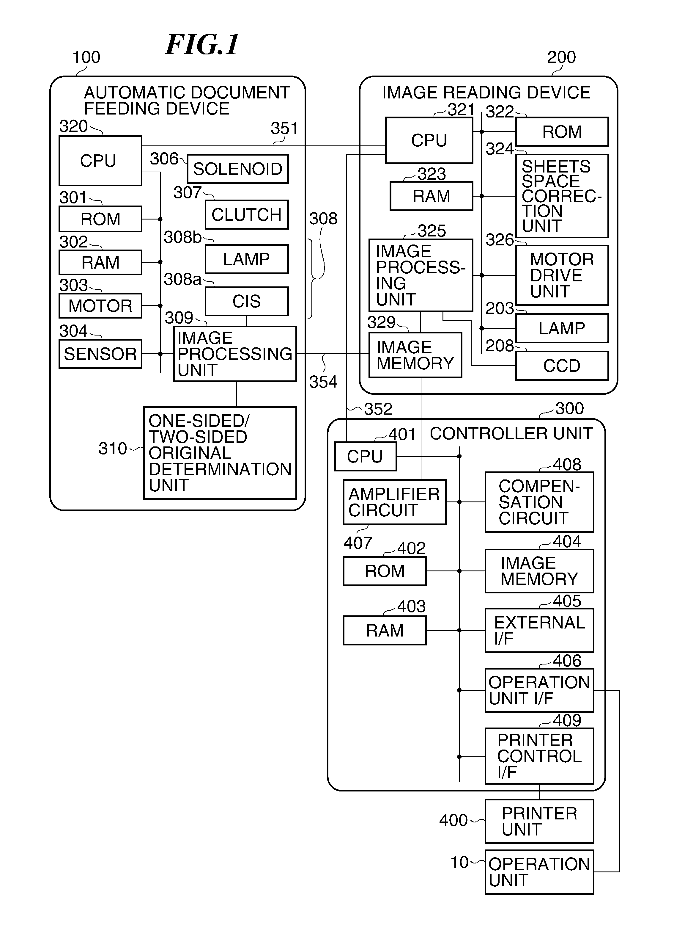
[0037]FIG. 1 is a block diagram schematically showing a configuration of a control system of an image forming apparatus according to an embodiment of the present invention.

[0038]This image forming apparatus is comprised of an operation unit 10, an automatic document feeding device 100, an image reading device 200, a controller unit 300, and a printer unit 400. The operation unit 10 controls a user interface such as reception of a key input and display of information. The automatic document feeding device 100 and the image reading device 200 can read images on both front and back sides of an original in parallel. The printer unit 400 has a function of printing a read original image. The controller unit 300 controls operations of the whole of the image forming apparatus.

[0039]A control system of the automatic document feeding device 100 is provided with a central ...


PUM


Abstract

An image forming apparatus which is capable of avoiding unnecessary switching operation to switch between a one-sided printing and a two-sided printing to improve print productivity. A printing mode is switched between a two-sided printing mode to continuously form images on first sides of a predetermined number of sheets and to alternately form images on second sides of sheets conveyed along a sheet re-feeding conveyance path and on the first sides of sheets fed from a sheet feeding unit, and a one-sided printing mode without using the sheet re-feeding conveyance path. It is determined that, when a one-sided print job is performed between a two-sided print jobs, whether the one-sided print job is performed in the two-sided printing mode as-is or in the one-sided printing mode, depending on whether the number of sheets continuously printed by the one-sided print job is more than a predetermined number.

Description

BACKGROUND OF THE INVENTION[0001]1. Field of the Invention[0002]The present invention relates to an image forming apparatus such as a copier and a control method therefor.[0003]2. Description of the Related Art[0004]In recent years an original image reading device that automatically feeds an original stacked on a document feeding device and reads images on front and back sides of the original concurrently in one pass through a conveyance path without turning the original upside down (e.g., see Japanese Laid-Open Patent Publication (Kokai) No. 2004-343409 (JP2004-343409A)) has been suggested. In such an original image reading device, a reading speed for a one-sided original on which an original image is formed on only one side is almost equal to that for a two-sided original on which original images are formed on both sides. Therefore, even if one-sided originals and two-sided originals are mixed in originals to be read, it is possible to read images at high speed without considering...

Claims


Application Information

Patent Timeline
Patent Type & Authority Patents(United States)
IPC IPC(8): G03G15/00
CPCG03G15/234G03G15/50H04N1/0057H04N1/0058H04N1/00602H04N1/0061H04N1/00615H04N1/00649H04N1/00657H04N1/203H04N1/2032G03G2215/00586G03G2215/0132
Inventor SAKAI, AKIHIKO
Owner CANON KK
Why Eureka
Try Eureka