
Safety needle assembly with passive pivoting shield

a safety needle and shield technology, applied in the direction of infusion needles, medical science, diagnostics, etc., can solve the problems of affecting patient comfort, affecting user comfort,

Active Publication Date: 2012-07-31
BECTON DICKINSON & CO
View PDF16 Cites 7 Cited by
  • Summary
  • Abstract
  • Description
  • Claims
  • Application Information

AI Technical Summary

Benefits of technology

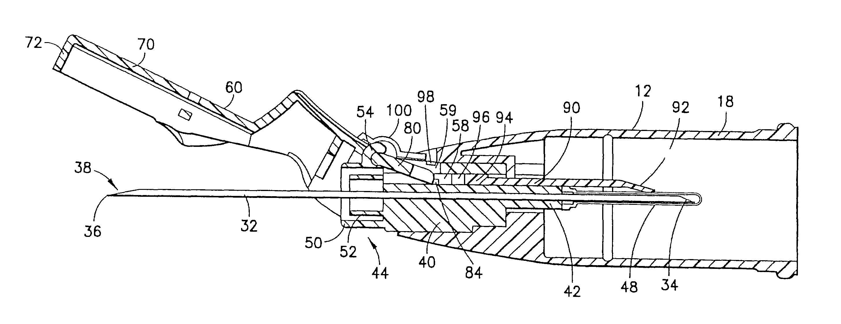
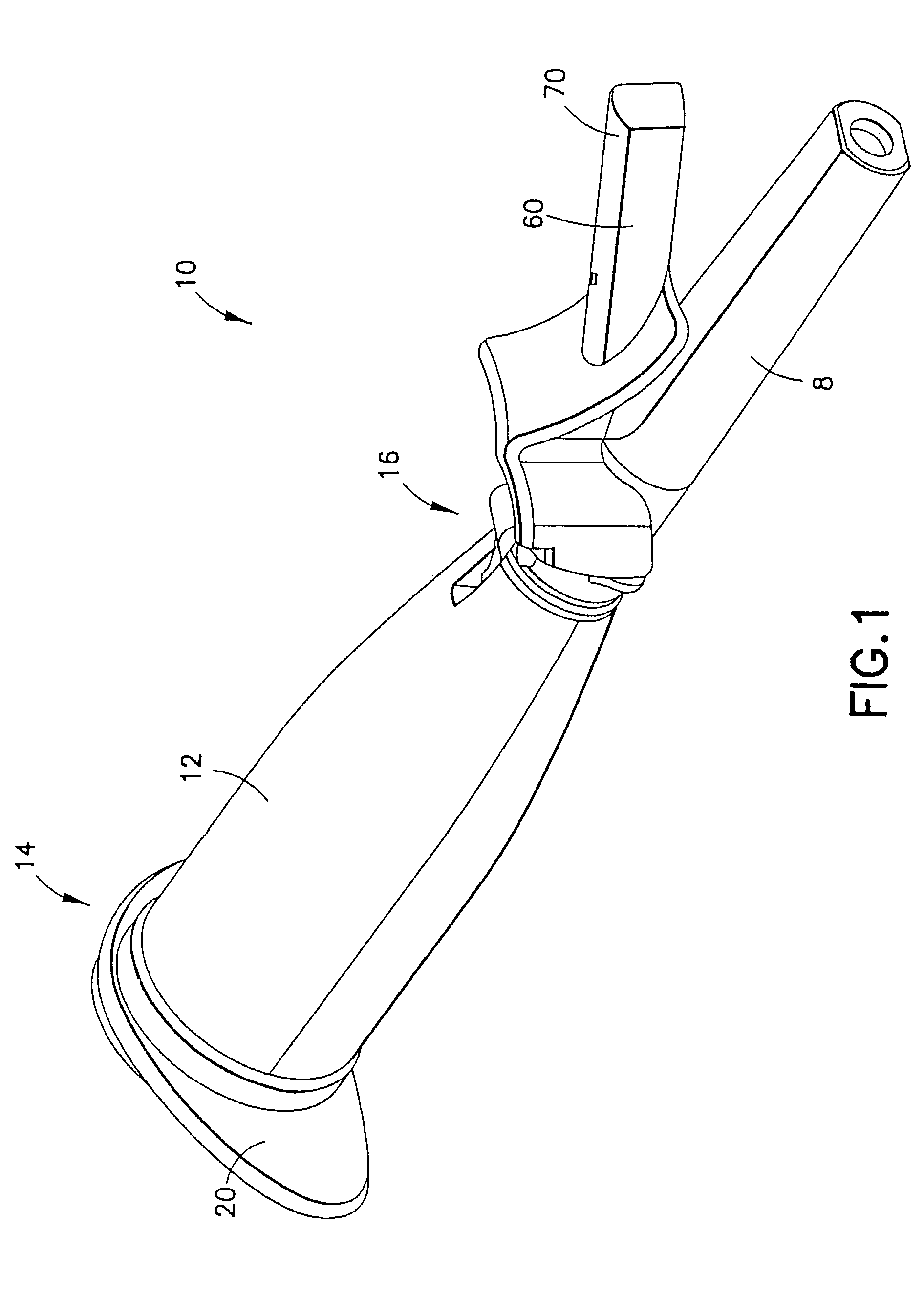
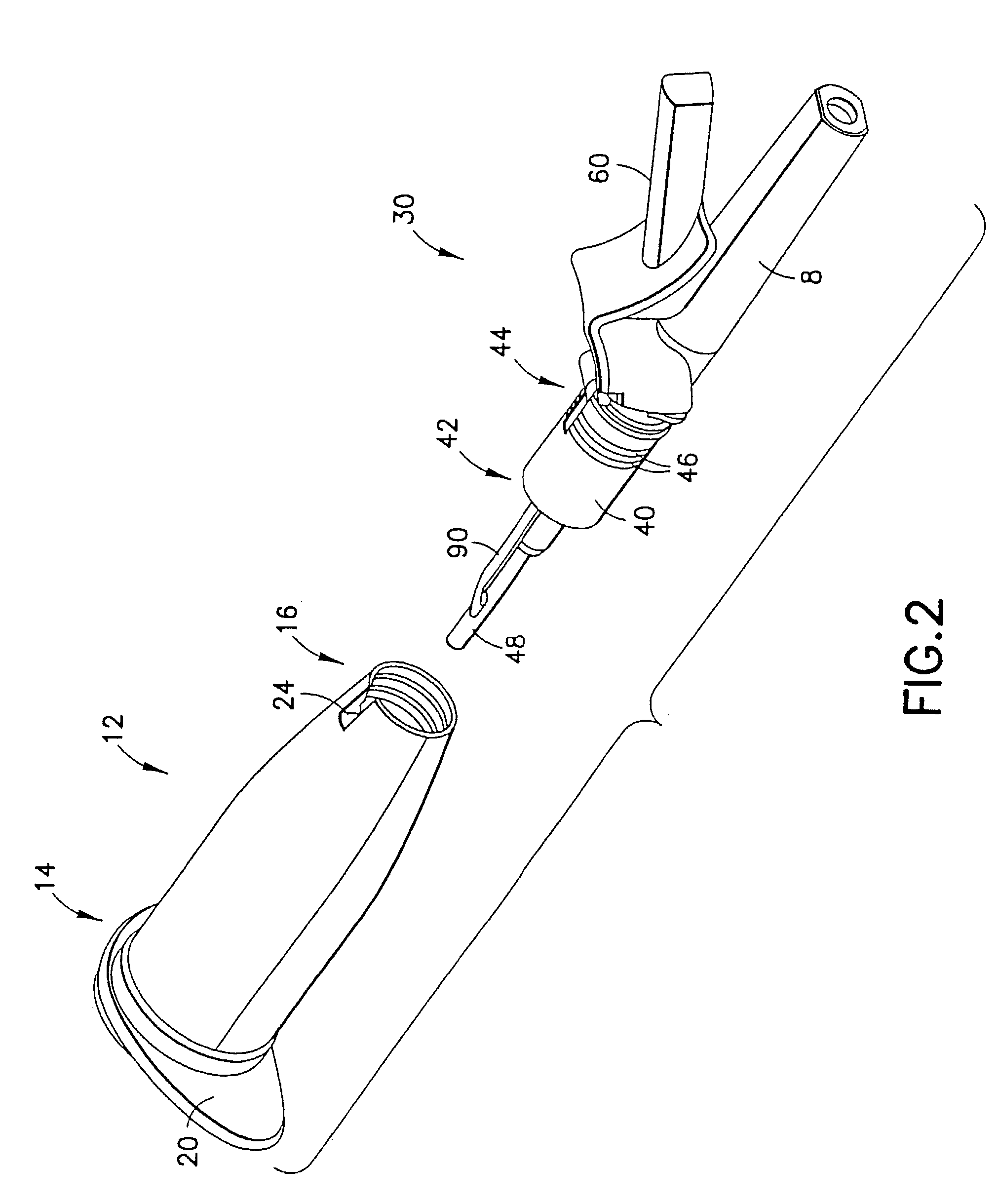
[0010]The present invention is further directed to a blood collection assembly including a needle assembly having a needle cannula, a hub mounted on the needle cannula, and a spring biased pivoting shield pivotably mounted to the hub and moveable about a pivot axis between a retracted position and a shielded position encompassing a distal end of the needle cannula. A needle holder is with the hub of the needle assembly, and is adapted for receiving a blood collection container such as an evacuated tube. A retaining member is attached to the pivoting shield and is releasably engageable with the hub to maintain the pivoting shield in the retracted position against the spring bias. Insertion of a blood collection tube into the needle holder causes the retaining member to release from engagement with the hub, thereby causing the pivoting shield to move toward the shielded position due to the spring bias.

Problems solved by technology

However, these shield arrangements typically require the use of one or two hands to perform the operation of moving the shield over the contaminated needle, which is a hindrance to the user.
While such assemblies provide effective needle shielding techniques, they involve complex mechanisms for activation, and deployment of the telescoping shield may disrupt the patient.

Method used


Image

  • Safety needle assembly with passive pivoting shield
  • Safety needle assembly with passive pivoting shield
  • Safety needle assembly with passive pivoting shield

Examples


Embodiment Construction

[0034]While this invention is satisfied by embodiments in many different forms, there is shown in the drawings and will herein be described in detail, the preferred embodiments of the invention, with the understanding that the present disclosure is to be considered as exemplary of the principles of the invention and is not intended to limit the invention to the embodiments illustrated. Various other modifications will be apparent to and readily made by those skilled in the art without departing from the scope and spirit of the invention. The scope of the invention will be measured by the appended claims and their equivalents.

[0035]It is noted that the term “distal” as used herein refers to the end of the assembly that punctures the patient's skin, while the term “proximal” as used herein refers to the opposing end of the assembly that punctures a collection container.

[0036]Referring to the drawings in which like reference characters refer to like parts throughout the several views t...


PUM


Abstract

A blood collection assembly includes a needle cannula, a hub mounted on the needle cannula, and a spring biased pivoting shield pivotably mounted to the hub and moveable about a pivot axis between a retracted position and a shielded position encompassing a distal end of the needle cannula. A needle holder is mated at a first end with the hub, and is adapted for receiving a blood collection container such as an evacuated tube through the opposing end. A retaining member is attached to the pivoting shield and is releasably engageable with the hub to maintain the pivoting shield in the retracted position against the spring bias. Insertion of a blood collection tube into the needle holder causes the retaining member to release from engagement with the hub, thereby causing the pivoting shield to move toward the shielded position due to the spring bias.

Description

BACKGROUND OF THE INVENTION[0001]1. Field of the Invention[0002]The present invention relates to a safety needle assembly with a pivoting shield that is activated during a standard sequence of operation of a medical procedure and, more particularly, relates to a needle and hub assembly having a pivoting shield that is passively pivoted to a shielding position when a sampling tube is inserted within a needle holder.[0003]2. Description of Related Art[0004]An evacuated collection tube, needle cannula (generally a double ended needle cannula) and needle holder are commonly used by a doctor, phlebotomist, or nurse to draw a sample of body fluid from a patient in a hospital or doctor's office for diagnostic testing. During the use of such a collection needle assembly, the distal end of the needle cannula in the needle holder is inserted in a vein of the patient. The evacuated collection tube is then inserted into the proximal end of the needle holder until a needle (the proximal end of a...

Claims


Application Information

Patent Timeline
IPC IPC(8): A61M5/32A61B5/15
CPCA61B5/1444A61M5/3219A61B5/15003A61B5/150351A61B5/150389A61B5/150572A61B5/150679A61B5/150732A61B5/154A61B5/150473A61B5/150717A61B5/150587A61M5/3216A61M2005/3217
Inventor SWENSON, KIRK D.
Owner BECTON DICKINSON & CO
Learn More