Power supply apparatus for slidable structure

a technology of power supply apparatus and sliding door, which is applied in the direction of insulated conductors, coupling device connections, cables, etc., can solve the problems of abnormal noise during automobile operation, poor operation performance of manually opening sliding doors, etc., and achieve the effect of suppressing unnecessary or excessive movement of wiring harnesses and decreasing the force needed

Active Publication Date: 2012-08-07
YAZAKI CORP +1
View PDF10 Cites 15 Cited by
  • Summary
  • Abstract
  • Description
  • Claims
  • Application Information

AI Technical Summary

Benefits of technology

[0014]The present invention is intended to provide a power supply apparatus for a slidable structure, capable of decreasing force needed to open the slidable structure, as well as, suppressing unnecessary or excessive movement of a wiring harness when the slidable structure is moved to its fully closed state.

Problems solved by technology

As a result, operation performance when manually opening the sliding door is poor.
Under such circumstances, because only small amount of tension or tensile force acts on the wiring harness 28, the wiring harness 28 possibly flip-flops, thereby creating abnormal noise while the automobile running.
The afore-mentioned drawbacks and problems are present in not only the sliding door of the automobile, but also the sliding door of a vehicle other than automobile, and sliding door of any apparatus other than a vehicle.

Method used


Image

  • Power supply apparatus for slidable structure
  • Power supply apparatus for slidable structure
  • Power supply apparatus for slidable structure

Examples


Embodiment Construction

[0019]One embodiment of a power supply apparatus for a slidable structure in accordance with the present invention will be described in more detail referring to the accompanying drawings.

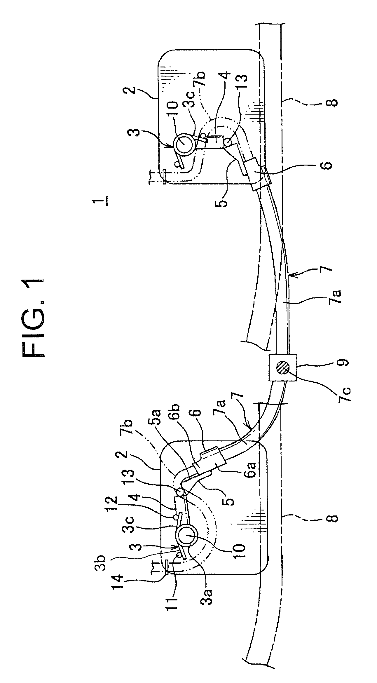
[0020]FIG. 1 shows one embodiment of a power supply apparatus for a slidable structure in accordance with the present invention. FIG. 1 shows the slidable structure in its fully closed state (right), and in its fully open state (left).

[0021]A power supply apparatus 1 has a torsion spring (i.e., an elastic member) 3 disposed on a upper posterior half portion of a vertical base plate 2, a ring arm 4 forward and upward biased by the torsion spring 3 in a counterclockwise direction, a second arm 5 disposed in the tip of the ring arm 4, and a wiring harness holding portion 6 disposed in the secondary arm 5. When a sliding door that is longitudinally disposed in a vehicle is fully closed, due to the tensile force of the wiring harness 7 the torsion spring 3 is greatly twisted downward and backward in a cl...


PUM


Abstract

A power supply apparatus for a slidable structure which extends longitudinally, including: a pivotably-supported ring arm; a wiring harness having one end portion fixed to a tip portion of the ring arm and the other end portion fixed to a stationary structure; and an elastic member configured to bias the ring arm in a forward and upward direction. The ring arm is moved or rotated in a backward and downward direction while elastically deforming the elastic member due to tensile force of the wiring harness, when the slidable structure is moved forward toward its fully closed state. Also, the ring arm is moved or rotated in a forward and upward direction due to restoring force of the elastic member, when the slidable structure is moved backward toward its fully open state.

Description

CROSS-REFERENCE TO RELATED APPLICATIONS[0001]The present Application claims priority to Japanese Patent Application No. 2009-081194 filed on Mar. 30, 2009, the entire disclosure of which is expressly incorporated herein by reference.BACKGROUND OF THE INVENTION[0002]1. Field of the Invention[0003]The present invention relates to a power supply apparatus for a slidable structure, for example, an apparatus for constant power supply via a wiring harness to a sliding door of a vehicle.[0004]2. Description of the Related Art[0005]FIG. 2 shows an example of conventional power supply apparatus for a slidable structure. See Japanese Publication of Patent Application No. 2008-148539A (in particular, FIGS. 8(c) and 10)[0006]This conventional power supply apparatus 41 has a pivotably-supported ring arm 43 inside an approximately trapezoidally-shaped protector 42, which is formed of synthetic resin, and is located in the sliding door of an automobile, and a metallic torsion spring for exerting a...

Claims


Application Information

Patent Timeline
Patent Type & Authority Patents(United States)
IPC IPC(8): H02G3/04
CPCB60R16/027H02G11/003
Inventor KATOU, MITSUNOBUNISHIMURA, TOMOAKIINAGAKI, MOTONARI
Owner YAZAKI CORP
Why Eureka
Try Eureka