Method and apparatus for controlling a focus lens

a focus lens and control method technology, applied in the field of focus lens control methods and apparatuses, can solve the problems of increasing scanning time, waste of power consumption, and conventional methods and apparatus for performing auto-focus functions, and achieve the effect of efficient and rapid movemen

Active Publication Date: 2012-08-07
SAMSUNG ELECTRONICS CO LTD
View PDF6 Cites 0 Cited by
  • Summary
  • Abstract
  • Description
  • Claims
  • Application Information

AI Technical Summary

Benefits of technology

[0008]The present invention provides a method of controlling a focus lens so that the focus lens can be moved efficiently and rapidly, an apparatus operating by the method, and a recording medium having recorded thereon a program to execute the method.

Problems solved by technology

There are disadvantages to this conventional method and apparatus for performing an auto-focus function.
Unnecessary movement of the focus lens causes problems, such as wasteful power consumption and an increase in scanning time.

Method used


Image

  • Method and apparatus for controlling a focus lens
  • Method and apparatus for controlling a focus lens
  • Method and apparatus for controlling a focus lens

Examples


Embodiment Construction

[0059]Now exemplary embodiments in accordance with the present invention will be described in detail with reference to the accompanying drawings.

[0060]According to the present invention, a target position of a focus lens is predicted using a normalized focus graph, so that the focus lens can be rapidly moved to the target position. An embodiment of the process for deriving a normalized focus graph is described with reference to FIGS. 1 through 8.

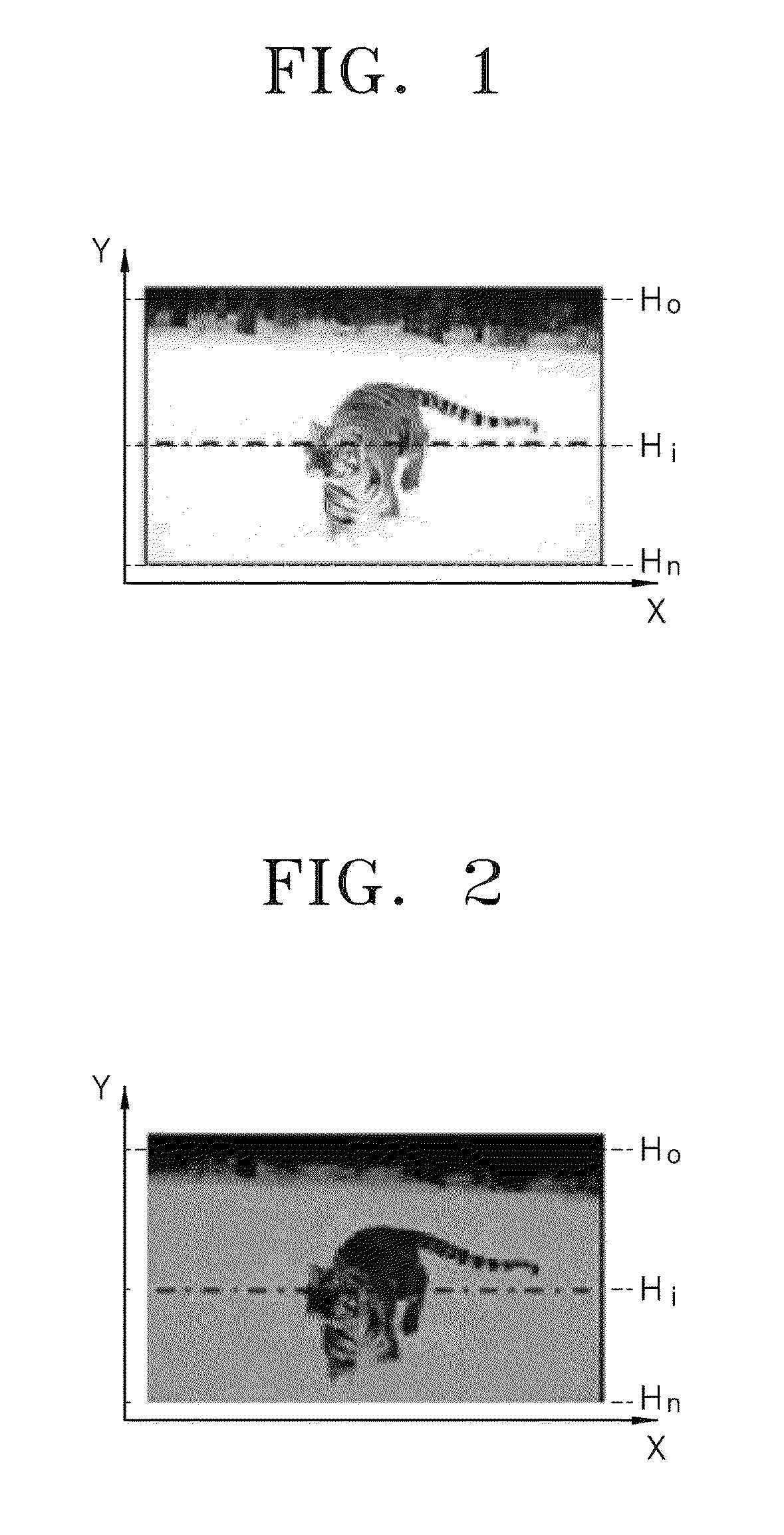
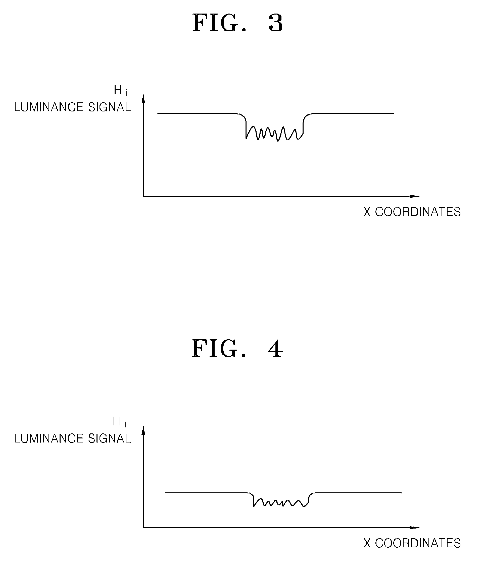
[0061]FIG. 1 is a first image of a subject (a tiger) and is a relatively bright image. FIG. 2 is a second image of the subject and is a relatively dark image compared to the first image of FIG. 1. That is, the first image has a high luminance level and the second image has a low luminance level.

[0062]In detail, FIG. 3 is a graph showing a luminance signal of a Hi line in the first image, and FIG. 4 is a graph showing a luminance signal of a Hi line in the second image. Comparing the two graphs, the luminance level of the first image is highe...


PUM


Abstract

Provided are a method of controlling a focus lens to be moved to a target location by generating a normalized focus graph by use of relative values of a plurality of focus values obtained by using a plurality of filters each having different cut-off frequencies, and predicting a target position of the focus lens according to the normalized focus graph, an apparatus operating by using the method, and a recording medium for recording the method. According to the present invention, in terms of performing an auto-focusing function, by optimizing the motion line of the focus lens, wasteful power consumption can be prevented and a scanning time of the focus lens can be shortened.

Description

CROSS-REFERENCE TO RELATED PATENT APPLICATION[0001]This application claims the benefit of Korean Patent Application No. 10-2008-0075327, filed on Jul. 31, 2008, in the Korean Intellectual Property Office, the disclosure of which is incorporated herein in its entirety by reference.BACKGROUND OF THE INVENTION[0002]1. Field of the Invention[0003]The present invention relates to a method of controlling a focus lens which is movable within a predetermined range so as to focus the focus lens on a subject, and an apparatus for controlling the focus lens by using the method.[0004]2. Description of the Related Art[0005]Recently, digital photographing apparatuses with an auto-focus function have been developed. The autofocus function performs focusing by analyzing image signals while moving a focus lens.[0006]A focus lens is typically movable between the limits of a far position (for focusing on distant objects) and a near position (for focusing on near objects). Conventionally, the auto focu...

Claims


Application Information

Patent Timeline
Patent Type & Authority Patents(United States)
IPC IPC(8): G03B13/00H04N5/232
CPCG03B13/32G02B7/28G03B13/36H04N9/28H04N23/55H04N23/67
Inventor KOH, SUNG-SHIKSUGIMOTO, KAZUHIKO
Owner SAMSUNG ELECTRONICS CO LTD
Why Eureka
Try Eureka