System and method for automatic mesh generation from a system-level MEMS design

a system-level, automatic technology, applied in the direction of design optimisation/simulation, instruments, error detection/correction, etc., can solve the problems of large computational effort, large amount of memory and processing time, and high computational cost, so as to achieve rapid and efficient movement, improve the effect of automatic mesh generation and optimization, and avoid considerable unnecessary computation

Active Publication Date: 2006-10-31
COVENTOR
View PDF16 Cites 44 Cited by
  • Summary
  • Abstract
  • Description
  • Claims
  • Application Information

AI Technical Summary

Benefits of technology

[0009]The illustrative embodiment of the present invention provides a mesh generation tool that is programmatically integrated with a system-level design and simulation environment, thereby enabling the direct generation of PDE solver input from a system-level design and simulation environment. Automatic mesh generation and optimization is improved by making available additional information about the nature and purpose of certain design components to the mesh generation tool. Specifically, the parameters of the components in the device schematic, which represent a user-defined decomposition of a larger MEMS design into smaller entities of clear physical purpose, are made available to the mesh generation tool. The link established between the system-level design and PDE analyses allows the user to rapidly and efficiently move between these two levels of abstraction. The mesh generation tool retrieves information from the components and connectors of a schematic of a MEMS device, and produces a discrete element model suitable for numerical PDE analysis by the finite element (FEM) and boundary element (BEM) methods. A direct link from a schematic model to a mesh model helps the user to produce an optimal mesh for PDE analysis, thereby avoiding considerable unnecessary computation.

Problems solved by technology

Unfortunately, the process of preparing a mesh in conventional CAD systems has several drawbacks.
Numerical PDE analysis tends to be very resource intensive from a computer standpoint, requiring considerable memory and processing time.
Each element type has strengths and weaknesses in its ability to conform to certain geometric shapes, the amount of computational effort required, and accuracy.
Using too fine a mesh or inappropriate element types can easily lead to impractically large memory and simulation time requirements.
Unfortunately, automatic algorithms require an extensive set of heuristics and therefore are inherently unreliable since they are not aware of the purpose and shape of sub-structures within the design and are unable to choose the optimal element type and local mesh density.

Method used


Image

  • System and method for automatic mesh generation from a system-level MEMS design
  • System and method for automatic mesh generation from a system-level MEMS design
  • System and method for automatic mesh generation from a system-level MEMS design

Examples


Embodiment Construction

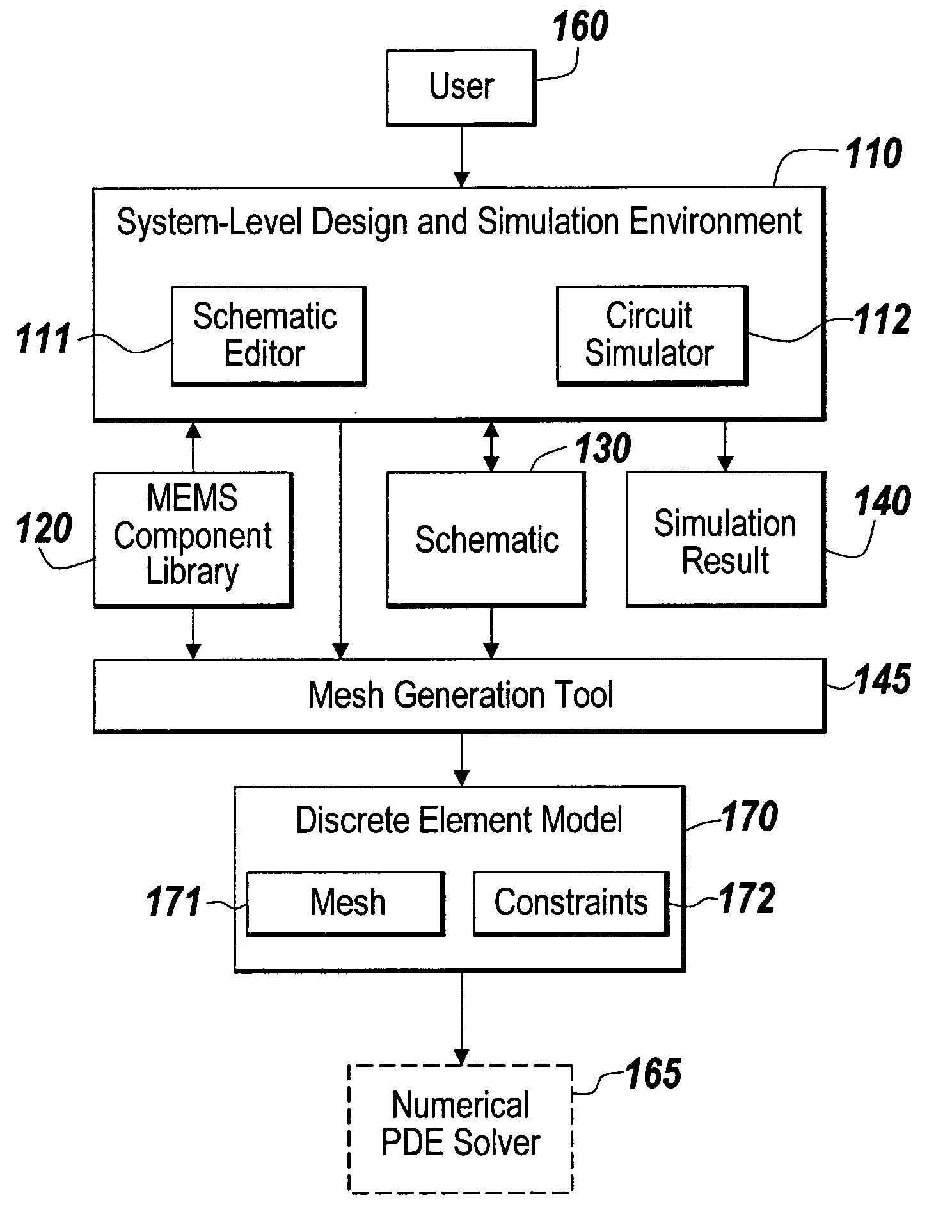
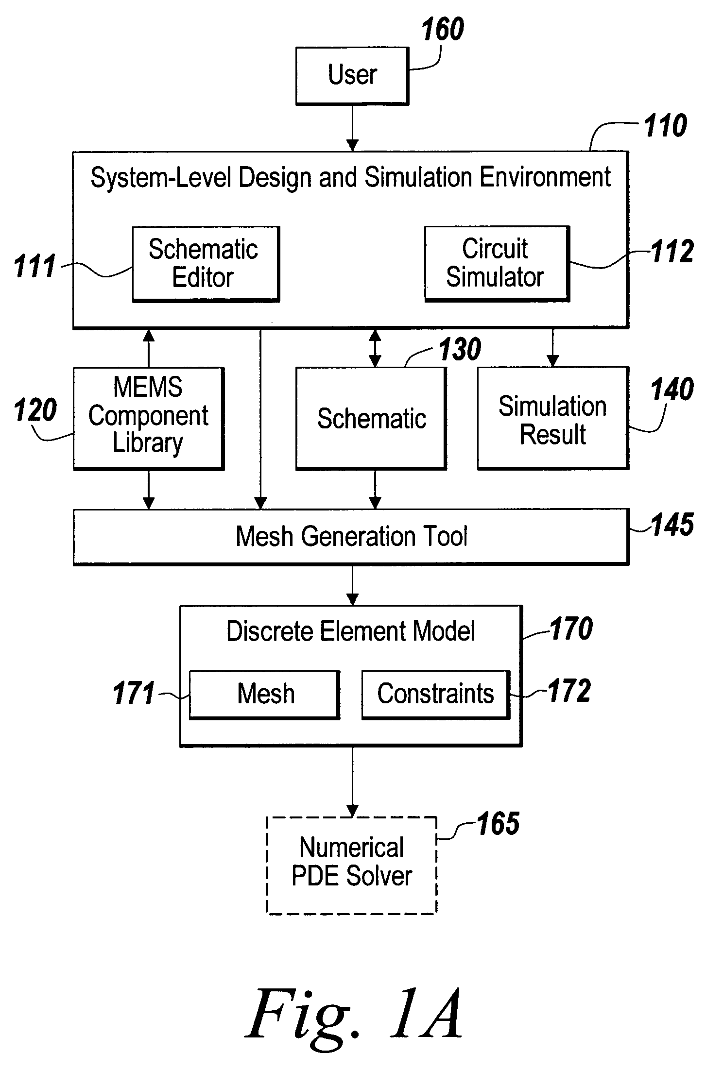
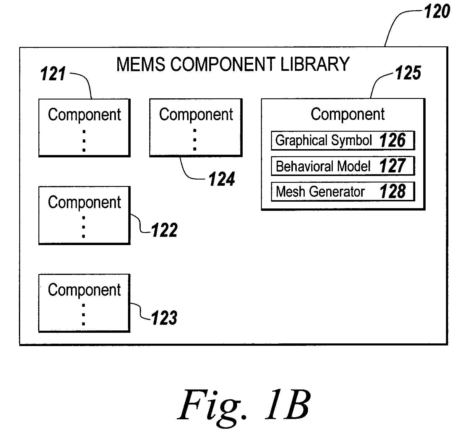
[0021]The illustrative embodiment of the present invention enables a user to create a schematic design, such as a MEMS design, which includes multiple components. Each component is associated with a mesh generator. Each mesh generator is a set of computer instructions describing how to create a mesh for the associated component. A mesh generation tool is utilized to access the multiple mesh generators to create a mesh representing either a device, or a sub-assembly of a device that is being modeled. The mesh is used as input to a solver, such as a numerical PDE solver, in a simulation environment. The direct use of the schematic avoids the loss of data that would follow from generating the mesh from a 2D mask layout or 3D solid model derived from the schematic.

[0022]FIG. 1A depicts a block diagram of an environment suitable for practicing the illustrative embodiment of the present invention. A user 160 interfaces with a System-Level Design and Simulation Environment 110 that include...


PUM


Abstract

A mesh generation tool that is programmatically integrated with a system-level design and simulation environment, thereby enabling the direct generation of PDE solver input from a system-level design and simulation environment and a method for using the mesh generation tool are disclosed. Automatic mesh generation and optimization is improved by making available additional information about the nature and purpose of certain design components to the mesh generation tool. Specifically, the parameters of the components in the device schematic, which represent a user-defined decomposition of a larger MEMS design into smaller entities of clear physical purpose, are made available to the mesh generation tool. The link established between the system-level design and PDE analyses allows the user to move between the two levels of abstraction. The mesh generation tool retrieves information from the components and connectors of a schematic of a MEMS device, and produces a discrete element model suitable for numerical PDE analysis by the finite element (FEM) and boundary element (BEM) methods. A direct link from a schematic model to a mesh model helps the user to produce an optimal mesh for PDE analysis, thereby avoiding considerable unnecessary computation.

Description

FIELD OF THE INVENTION[0001]The illustrative embodiment of the present invention relates generally to Computer Aided Design (CAD) and more particularly to automatic mesh generation from a system-level design and simulation environment thereby making it easier to verify approximations made in a schematic-driven Micro Electro-Mechanical Systems (MEMS) design with detailed 3D numerical analysis of the governing partial differential equations (PDEs).BACKGROUND[0002]Computer Aided Design (CAD) systems are used to design and simulate virtual models of electrical, electronic or mechanical devices prior to producing actual physical devices. CAD systems are interactive software tools that run on a digital computer with a graphical display device. In particular, micro-fabricated devices such as electronic integrated circuits (ICs) and Micro Electro-Mechanical Systems (MEMS) can be designed and simulated using CAD systems prior to beginning the costly and time-consuming process of fabricating ...

Claims


Application Information

Patent Timeline
Patent Type & Authority Patents(United States)
IPC IPC(8): G06F17/50G06F7/60
CPCG06F17/5018G06F30/23
Inventor LORENZ, GUNARKENNEDY, CHRISTOPHER J.
Owner COVENTOR
Why Eureka
Try Eureka