Synchronizing cylinder for extruder

a synchronizing cylinder and extruder technology, applied in the direction of servomotors, servomotor components, servometer circuits, etc., can solve the problems of flow technology disadvantage, and achieve the effect of efficient and rapid movement, efficient and rapid movement of the plan

Active Publication Date: 2020-06-02
SMS GRP GMBH +1
View PDF19 Cites 2 Cited by
  • Summary
  • Abstract
  • Description
  • Claims
  • Application Information

AI Technical Summary

Benefits of technology

[0006]An object of the invention consists of providing a double-rod ram which with a compact, long-life mode of construction is movable in a low-loss manner, efficiently and rapidly by an external drive, preferably an electric motor or a pneumatic motor or, however, a hydraulic cylinder or the like. A further object consists of indicating shaping equipment, preferably a press, extruder or ring roller, which with a compact long-life mode of construction realizes an efficient and rapid movement of the plant between a work configuration and one or more other configurations.SUMMARY OF THE INVENTION
[0008]In addition, the double-rod ram comprises a bypass device with at least one, preferably two, bypass valves. The above-mentioned annular gap and / or the at least one bypass line is or are a component of the bypass device. The bypass device is so arranged that in a specific setting or position of the bypass valve, here termed bypass position, a fluid connection is formed between the two compartments via the annular gap and / or the at least one bypass line and in another setting or position of the bypass valve, here termed work position, no such fluid connection (within the double-rod ram) is formed. In other words, the bypass position allows a fluid exchange between the compartments in that hydraulic fluid flows from one compartment via the annular gap and / or the at least one bypass line to the other compartment, whereas such a fluid exchange is precluded in the work position. The described double-rod ram has a compact form of construction in which a circumventing function, also termed bypass function, is realized in a technically simple way. The annular duct formed by the concentric cylinders, i.e. inner cylinder and outer cylinder, allows a low-loss bypass flow. The same also applies, additionally to the annular duct or alternatively thereto, to the at least one bypass line outside the cylinder housing. The work piston can thus be moved by an external drive in energy-saving manner, with low loss and rapidly. By virtue of the synchronous mode of construction, the hydraulic cylinder can develop the full rated force in every stroke position.
[0009]Due to the above-described technical effects and advantages the double-rod ram is particularly advantageous in the field of shaping equipment, particularly presses, extruders or ring rollers. The extruders in that case have a lifted-out position, since a rapid movement of the receiver or in a given case other plant parts over a large stroke is desirable there. The double-rod ram according to the invention then combines, in synergetic manner, a work operation and a towed operation over the entire stroke. In particular, the double-rod ram can, over the entire stroke, be switched over between work operation and towed operation, thus the operation in which the bypass valve is brought into the bypass position and the double-rod ram is moved by an external drive, for example one or more electric motors. The flow losses and the internal friction of the double-rod ram are then reduced so that the towed operation can be carried out in force-saving manner, efficiently in terms of energy and rapidly.
[0010]The piston rod is preferably designed so that it extends on both sides from the work piston and has the same diameter on both sides. In this way the double-rod ram can be realized in a technically particularly simple manner, since in the case of a cylindrical work piston the contact surfaces for loading with the hydraulic fluid are of the same size on both sides. It is possible to dispense with a hollow-cylindrical piston, which is disadvantageous in terms of flow technology. In that regard, for preference the bypass valve is guided on the piston rod, preferably annularly surrounding the piston rod, and for switching over between the bypass position and a work position the bypass valve is in this case axially displaced. The piston rod is thus used synergetically as a guide and therefore, so to speak, as a component of the bypass valve. The technical construction of the double-rod ram is thereby simplified and susceptibility to fault reduced.
[0013]The bypass device preferably comprises two bypass valves provided at the opposite sides of the work piston. The bypass path can thereby be realized in technically simple manner by the annular gap and / or the at least one bypass line. In that case, with particular preference a substantially mirror-symmetrical construction of the bypass valve is used, in a given case of the entire double-rod ram, in order to homogenize the force characteristics. The bypass valve or bypass valves is or are preferably provided at the end regions or the head sides of the double-rod ram, whereby the stroke is maximized. The bypass valves can provide, together with the piston surfaces and the inner cylinder, a part of those walls which form the compartments.
[0016]The cylinder head supports can be components which not only contribute to creation and definition of the bypass device, preferably of the annular gap, but also can carry or include the hydraulic fluid lines. As a further function they can assist the technical construction of the bypass valves, because the bypass valves are preferably in contact not only with the piston rod, but also with the corresponding cylinder head support. The construction of the double-rod ram is thus substantially simplified and its susceptibility to fault reduced.

Problems solved by technology

It is possible to dispense with a hollow-cylindrical piston, which is disadvantageous in terms of flow technology.

Method used


Image

  • Synchronizing cylinder for extruder
  • Synchronizing cylinder for extruder
  • Synchronizing cylinder for extruder

Examples


Embodiment Construction

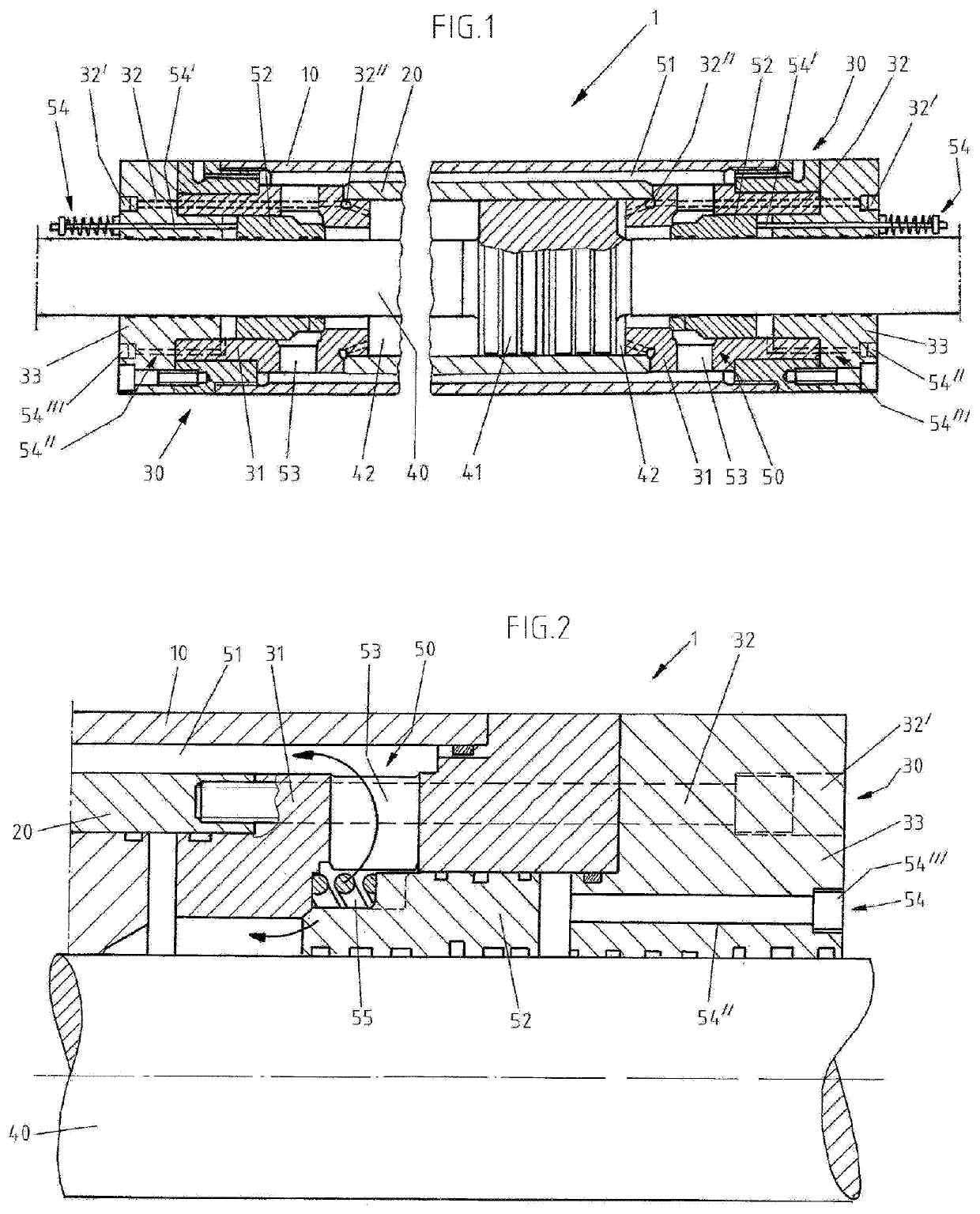
[0024]Preferred embodiments are described in the following on the basis of FIG. 1. In that case identical, similar or equivalent elements are provided with identical reference numerals and repeated description of these elements is partly dispensed with so as to avoid redundancies.

[0025]FIG. 1 shows a double-rod ram 1. More precisely, the two ends of the cylinder 1 are shown in longitudinal section that in the present embodiment are constructed substantially in mirror symmetry.

[0026]The hydraulic cylinder 1 has a hollow outer cylinder 10, a hollow inner cylinder 20, and on each of the left and the right a head section 30 and a piston rod 40 with a work piston 41 integrated therein or connected therewith. The head section 30 has a cylinder head support 31 and a cylinder closure 33, whereby the hydraulic cylinder 1 is closed at both ends and the inner cylinder 20 is fixed relative to the outer cylinder 10. The inner cylinder 20 is inserted into the outer cylinder 10 and the two lie con...


PUM


Abstract

A double-rod ram (1), preferably for an extruder, comprising an outer cylinder (10), an inner cylinder (20) installed therein and arranged concentrically therewith, a double-acting work piston (41) provided in the inner cylinder to be displaceable and a bypass device (50) with at least one bypass valve (52), wherein the work piston (41) divides the inner cylinder (20) into two compartments (42) and can be loaded with a hydraulic fluid from both compartments (42), wherein the bypass device (50) is so arranged that in a bypass position of the bypass valve (52) a fluid connection between the two compartments (42) is formed by a direct connection, preferably at least one bypass line, and in a work position of the bypass valve (52) no such fluid connection is present.

Description

CROSS REFERENCE TO RELATED APPLICATIONS[0001]This application is the US-national stage of PCT application PCT / EP2017 / 052135 filed 1 Feb. 2017 and claiming the priority of German patent application 102016202357.8 itself filed 16 Feb. 2016 and German patent application 102016214767.6 itself filed 9 Aug. 2016.FIELD OF THE INVENTION[0002]The invention relates to a double-rod ram, preferably for use in a shaping apparatus, particularly a press, extruder or ring roller.BACKGROUND OF THE INVENTION[0003]Extruders and ring rollers are devices for plastic shaping of materials, for example preheated heavy-metal or light-metal ingots, by a selective application of force. Thus, in the case of an extruder, for example, such a heavy-metal or light-metal ingot, also termed billet, is driven by a hydraulically operated press ram through a so-called die, whereby a semi-finished product with a specific defined profile is produced. Such extruders are evident from, for example, DE 38 36 702 C1 and DE 10...

Claims


Application Information

Patent Timeline
Patent Type & Authority Patents(United States)
IPC IPC(8): F15B13/02F15B15/14F15B15/20F15B11/22
CPCF15B15/1428F15B15/202F15B13/021F15B11/22F15B15/149F15B2211/7054
Inventor KLINGEN, HERMANN-JOSEFMUSCHALIK, UWESIEMER, EKHARDCLAASEN, KARL HERRMANNGALA LOSADA, VALENTINWERSHOFEN-CROMBACH, ANDREAS
Owner SMS GRP GMBH
Why Eureka
Try Eureka