Communication apparatus

a technology of communication apparatus and communication device, which is applied in the direction of substation equipment, devices with touch pads/sensors/detectors, instruments, etc., can solve the problems of short endurance period, need for maintenance of operation detection units,

Active Publication Date: 2012-08-07
KYOCERA CORP
View PDF7 Cites 147 Cited by
  • Summary
  • Abstract
  • Description
  • Claims
  • Application Information

AI Technical Summary

Benefits of technology

[0022]With a communication apparatus according to the present invention, since a control unit controls at least either a signal processing unit or an operation detecting unit when processing by the signal processing unit of a signal transmitted or received by an antenna and output of an oscillation signal by an oscillating unit of the operation detecting unit are performed concurrently, it is now possible to suppress the incorporation of an oscillation signal outputted by the oscillating unit of the operation detecting unit as noise into a signal transmitted or received by the antenna.

Problems solved by technology

However, with such a conventional technique, the use of a “rotary dial” that involves physical and mechanical rotation is likely to cause malfunctions, failures and the like due to mechanical attrition and the like, giving rise to problems such as the need for performing maintenance on an operation detecting unit, a short period of endurance, and the like.

Method used


Image

  • Communication apparatus
  • Communication apparatus
  • Communication apparatus

Examples


first embodiment

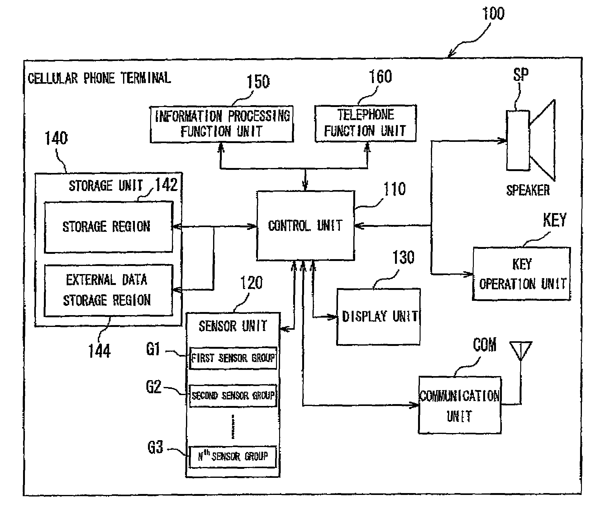
[0063]Next, a description will be given on a confirmation operation on whether or not the touch sensor is to be activated performed by the touch sensor driver upper application program interface API, which is a first embodiment of the present invention. As described above, when a touch sensor is disposed in a communication apparatus configured so as to include an antenna that transmits or receives a signal, in the event that the frequency of an oscillation signal outputted by the oscillating unit and the frequency of a signal transmitted or received by the antenna are similar in value, the oscillation signal outputted by the oscillating unit may become inadvertently incorporated as noise into the signal transmitted or received by the antenna. The present invention is arranged so that when the base application BA requests the touch sensor driver upper application program interface API to activate the touch sensor, the touch sensor driver upper application program interface API checks...

second embodiment

[0074]Next, a description will be given on operations of a cellular phone terminal 100 in a case where a touch sensor is used during radio reception. In the case where a sensor unit 120 including an oscillating unit is provided in a communication apparatus such as the cellular phone terminal 100 which is configured so as to include an antenna that transmits or receives an electromagnetic wave or a radio antenna capable of receiving an electromagnetic wave containing a broadcast signal of a radio broadcast, when the frequency of an oscillation signal outputted by the oscillating unit is similar in value to the frequency of an electromagnetic wave transmitted or received by the antenna or the frequency of an electromagnetic wave received by a television antenna or the radio antenna, not shown, there is a risk that the oscillation signal outputted by the oscillating unit becomes incorporated into an electric signal based on the electromagnetic wave transmitted or received by the antenn...


PUM


Abstract

A communication apparatus includes: a communication unit COM that performs operation control of a function involving transmission or reception of an electromagnetic wave by an antenna; a touch sensor module TSM having an oscillation circuit and an electrode connected to the oscillation circuit; a power supply PS that supplies power to the oscillation circuit; and a power supply controller PSCON that controls supply of power by the power supply PS. The touch sensor module TSM detects a contact operation based on an oscillation state of the oscillation circuit which varies in accordance with a contact operation. As a result, a state where the power supply PS is supplying power to the oscillation circuit under the control of the power supply controller PSCON and a state where the communication unit COM is performing operation control of the function involving transmission or reception of an electromagnetic wave do not exist concurrently.

Description

TECHNICAL FIELD[0001]The present invention relates to a communication apparatus, and more particularly, to a communication apparatus provided with an antenna, a signal processing unit that processes signals transmitted or received by the antenna, and an operation detecting unit.BACKGROUND ART[0002]Conventionally, various interfaces and configurations have been developed as operation detecting units of communication apparatuses. For example, there is a technique in which a communication apparatus is provided with a rotary dial-type input device, wherein a cursor displayed on a display unit is moved in accordance with the amount of rotation of the rotary dial-type input device (refer to Patent Document 1). However, with such a conventional technique, the use of a “rotary dial” that involves physical and mechanical rotation is likely to cause malfunctions, failures and the like due to mechanical attrition and the like, giving rise to problems such as the need for performing maintenance...

Claims


Application Information

Patent Timeline
Patent Type & Authority Patents(United States)
IPC IPC(8): H04B1/40H04B15/00H04M1/00H04M1/72442
CPCH04B1/40H04B15/02H04B2215/062H04M1/67H04M2250/16H04M2250/22H04M1/72442G06F3/041
Inventor IIO, TAROOMURA, SATOKO
Owner KYOCERA CORP
Why Eureka
Try Eureka