
Aircraft-fuselage assembly concept

a fuselage and assembly technology, applied in the direction of fuselages, sustainable transportation, transportation and packaging, etc., can solve the problems of destroying the fuselage structure, affecting so as to improve the stability of the fuselage section

Inactive Publication Date: 2012-08-14
AIRBUS OPERATIONS GMBH
View PDF24 Cites 5 Cited by
  • Summary
  • Abstract
  • Description
  • Claims
  • Application Information

AI Technical Summary

Benefits of technology

The present invention provides a new design for the fuselage of an aircraft that is easier and more economical to implement than previous designs. The new design uses a separate passenger cabin and cargo compartment, each with its own separate tube. These tubes are enclosed by an exterior tube that is non-positively connected to them. The interior tubes are designed as supporting shell constructions, with the loads experienced during flight being transferred through the tubes themselves, rather than through the skeleton structure of frames and ribs. The interior tubes are enclosed by a first plurality of circumferential straps and a second plurality of circumferential straps to provide stability and space between the exterior tube and the interior tubes. The straps are produced in an upstream production step and are designed with alignment tabs to position the interior tubes in a specified position relative to each other. The new design allows for a simpler and more efficient assembly process and provides greater stability and space between the tubes.

Problems solved by technology

In this known type of fuselage assembly the fuselage is thus made from a large number of individual components (frames, stringers, exterior skin fields) in a complex assembly process, as a result of which considerable costs arise already during assembly of the fuselage.
Apart from these difficulties relating to production technology, there is a further disadvantage in that both the passenger cabin and the cargo compartment, due to the low air pressure at high altitudes, have to be pressurised during the flight.
It is therefore necessary that in the case of decompression (drop in pressure) in the passenger compartment or cargo compartment, which decompression can, for example, be caused by damage to the exterior skin at high altitude, rapid pressure equalisation between these two spaces occurs, because otherwise the fuselage structure can be destroyed as a result of the pressure acting unilaterally on the floor grid, which floor grid is not designed to withstand such loads.
In order to ensure pressure equalisation, pressure equalisation flaps are thus normally installed on the sides of the floor along the entire length of the fuselage, which pressure equalisation flaps are, however, associated with a further disadvantage in that in the case of an emergency landing on water, water enters the entire fuselage particularly quickly by way of this connection.

Method used


Image

  • Aircraft-fuselage assembly concept
  • Aircraft-fuselage assembly concept
  • Aircraft-fuselage assembly concept

Examples


Embodiment Construction

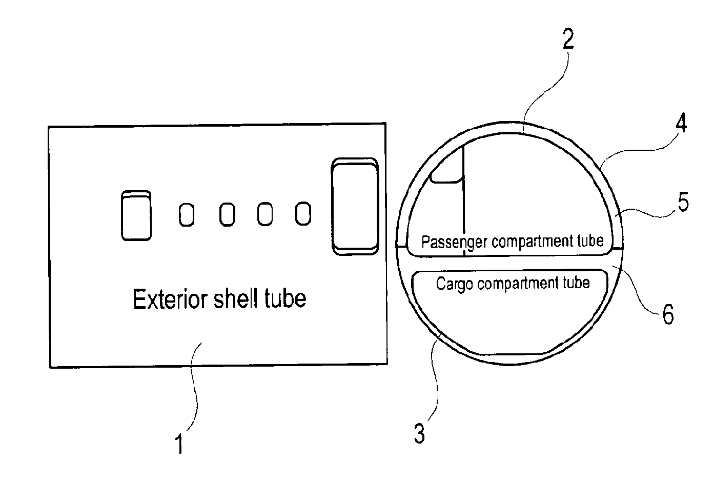
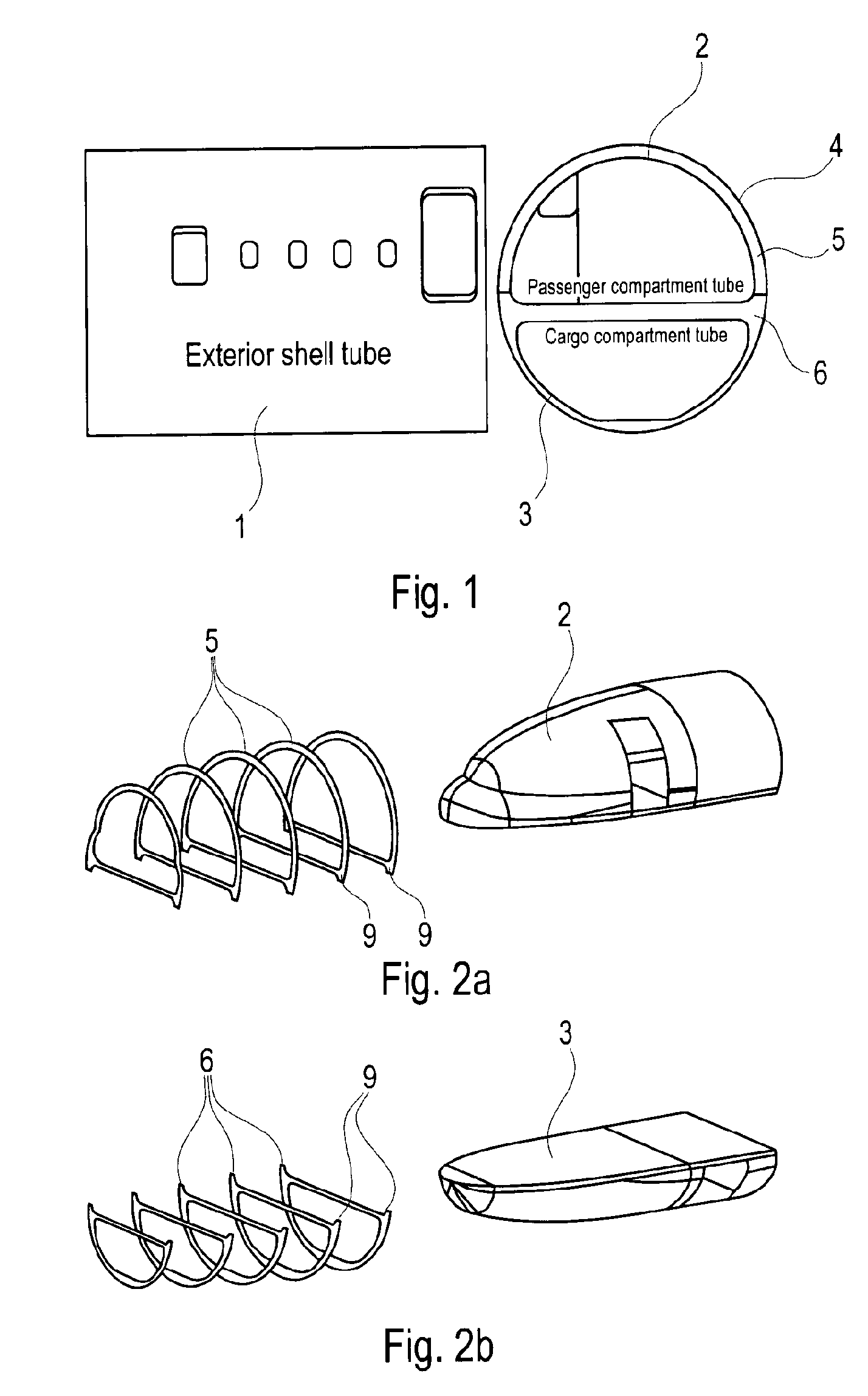
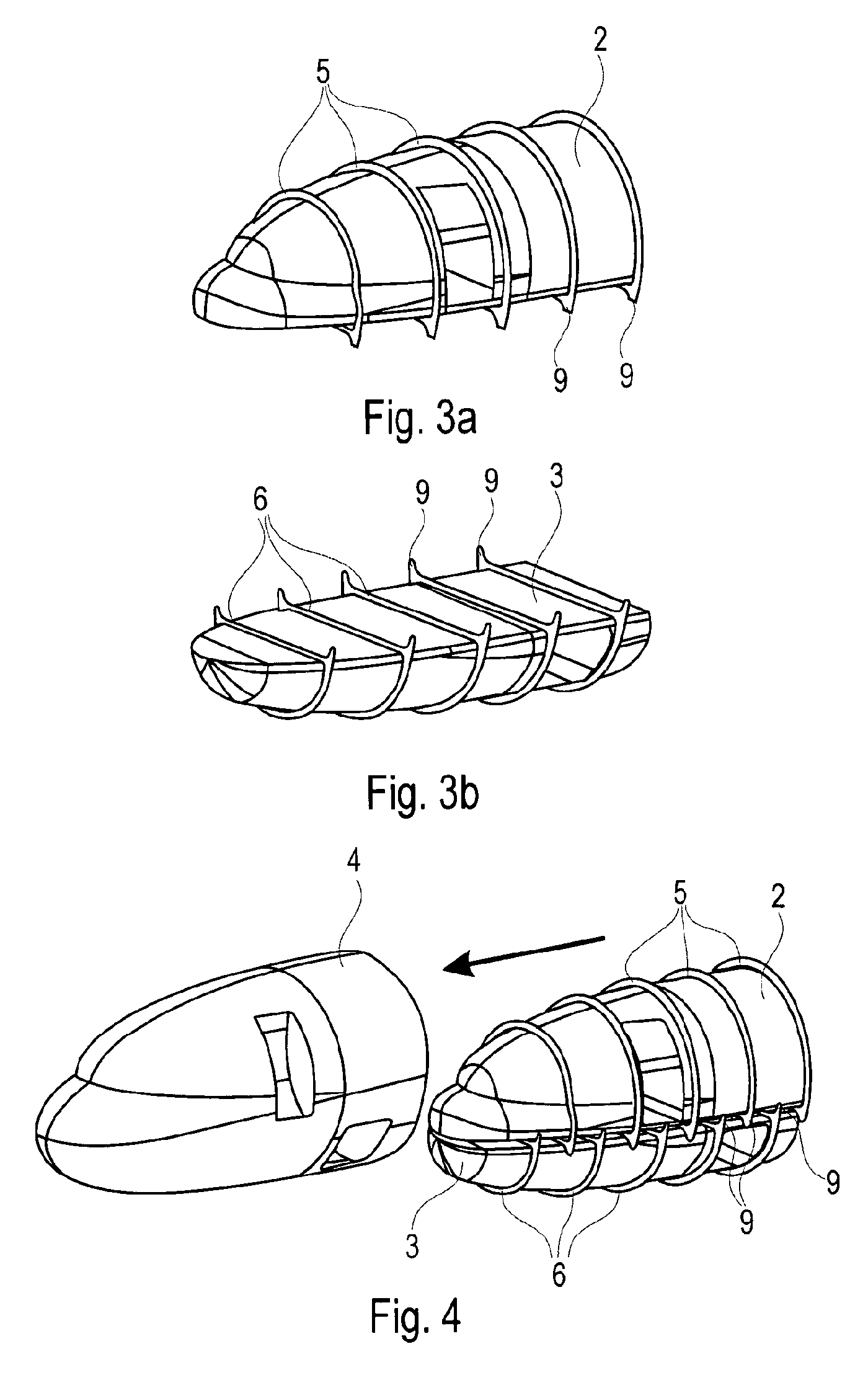
[0030]FIG. 1, and in particular the right-hand diagram, shows a basic principle of the invention, according to which the fuselage section 1 according to the invention essentially comprises or consist of three different tubes 2, 3, 4 that are produced in separate steps and are joined only during final assembly of the fuselage. The fuselage section 1 thus comprises or consist of an exterior tube 4 that encloses the two interior tubes 2 and 3 that have been fitted into it, as shown in the right-hand diagram of FIG. 1. In this arrangement the first interior tube 2 forms a passenger cabin section while the second interior tube 3 forms a corresponding cargo compartment section. As shown in the right-hand diagram of FIG. 1 the two interior tubes 2 and 3 are arranged in the interior of the exterior tube so as to be spaced apart from each other, wherein the flat floor region of the first tube extends essentially in parallel to the flat ceiling region of the second tube 3. Spacing apart the t...


PUM

PropertyMeasurementUnit
face areasaaaaaaaaaa
air pressureaaaaaaaaaa
altitudeaaaaaaaaaa

Abstract

An aircraft fuselage section includes a first interior tube as well as a second interior tube that are produced in an upstream production step, which interior tubes are subsequently enclosed by an exterior tube. For spacing and in order to provide more stability to the tubes the interior tubes are enclosed by straps that are arranged between the interior tubes and the exterior tube.

Description

TECHNICAL FIELD[0001]The present invention relates to the technical field of aircraft fuselage assembly. In particular, the invention relates to a fuselage section which, with the use of a novel assembly method, is essentially made of three tubes. Furthermore, the invention relates to a fuselage that has been joined from several fuselage sections according to the invention.BACKGROUND TO THE INVENTION[0002]Nowadays the assembly of modern aircraft fuselages usually takes place in that a plurality of vertical frames in longitudinal direction of a fuselage are connected to a plurality of horizontal stringers that are aligned, so as to be essentially perpendicular to said vertical frames, to form a skeleton, whereupon on the outside the individual exterior skin fields of the fuselage are riveted on or bonded on. In this process the fuselage is not produced in a continuous piece; instead, at first individual fuselage sections (also known as barrels or segments) are formed, which sections ...

Claims


Application Information

Patent Timeline
Patent Type & Authority Patents(United States)
IPC IPC(8): B64C1/00
CPCB64C1/061B64C1/068Y10T29/49622B64C2001/0081Y02T50/433B64C2001/0072Y02T50/40B64C1/0683B64C1/0685
Inventor PAHL, GUNTER
Owner AIRBUS OPERATIONS GMBH
Learn More