Printing head

a printing head and printing element technology, applied in the field of printing heads, can solve the problems of printing failure, undesirable deformation and serious influence of deformation on printing quality, and achieve the effect of small deformation amount of the printing element substra

Active Publication Date: 2012-08-14
CANON KK
View PDF8 Cites 2 Cited by
  • Summary
  • Abstract
  • Description
  • Claims
  • Application Information

AI Technical Summary

Benefits of technology

[0013]According to the above-described configuration, when the printing head is erroneously fallen from an elevated place, the region in which the concave portion is formed on the rear surface side of the sheet-shaped portion becomes likely to deform because the stiffness becomes small as compared with cases where the concave portion is not formed on the rear surface side. Therefore, the deformation amount of the region, in which the printing element substrate is secured, of the sheet-shaped portion can be suppressed, and the amount of deformation pertaining to the printing element substrate can be suppressed.

Problems solved by technology

Accordingly, for example, in mounting the printing head to the printing apparatus, if the printing head accidentally falls from an elevated place and the above-described portion having poor strength of the printing head receives an impact, the printing element substrate provided in the printing head may be damaged to cause printing failures.
Such deformation of the printing element substrate is undesirable because the deformation affects the printing quality.
Particularly, in cases where a rectangular ink supply port extending through the printing element substrate is provided in the printing element substrate, if the printing element substrate deforms due to an impact applied to the printing head, this deformation may have serious influence on the printing quality.
If this deformation becomes excessive, a crack may occur in the printing element substrate.
A crack in the printing element substrate may disconnect wirings and the like inside the printing element substrate, causing printing failures.

Method used


Image

  • Printing head
  • Printing head
  • Printing head

Examples


first embodiment

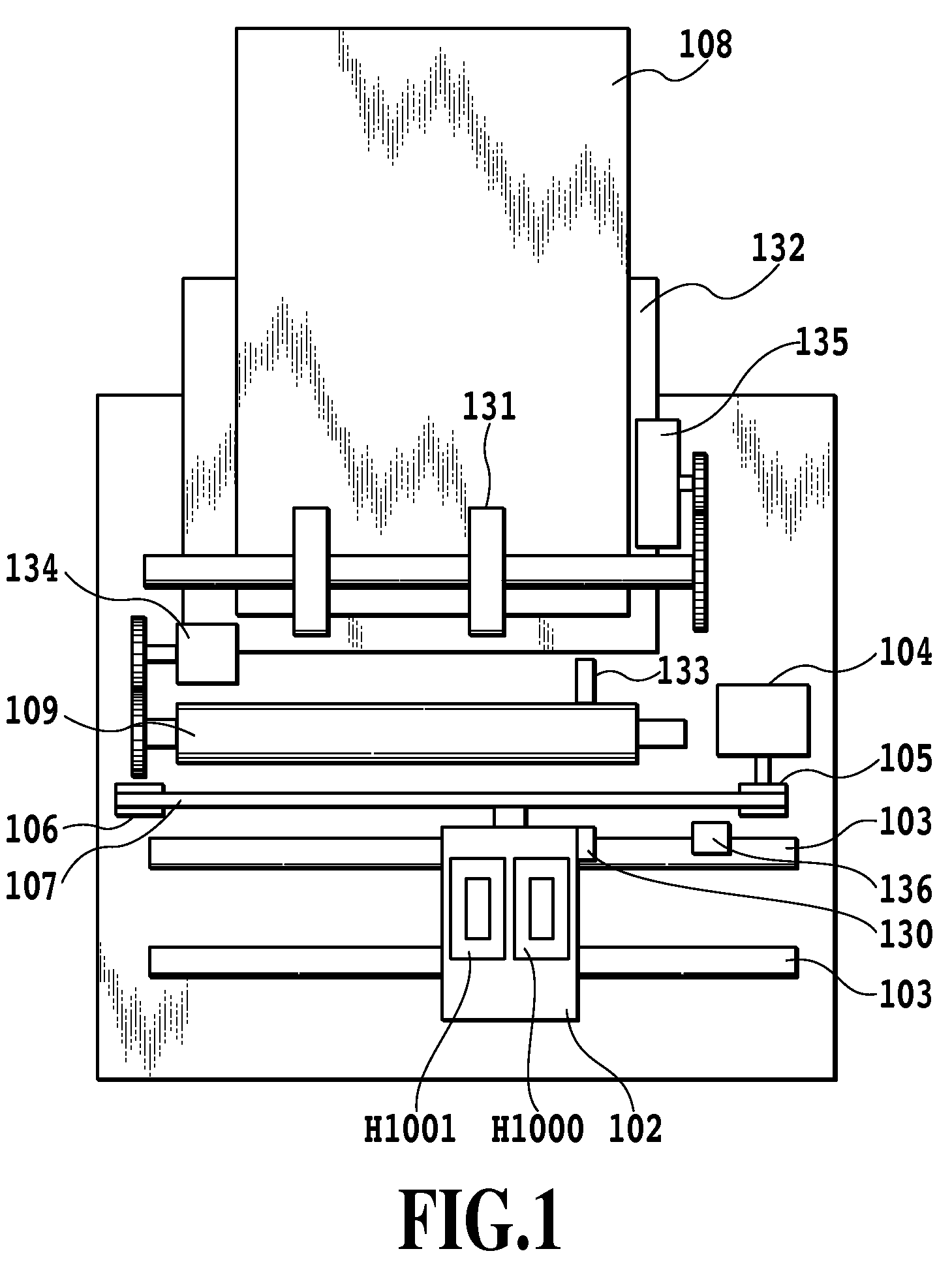
[0037]FIG. 1 is a schematic structural view showing a configuration of an inkjet printing apparatus in an embodiment of the present invention. The inkjet printing apparatus repeats an operation of reciprocating a first printing head H1000 and a second printing head H1001 in a main-scanning direction and an operation of conveying a printing medium 108 in a sub-scanning direction at every predetermined pitch. In synchronization with these movements, ink is selectively ejected from the first printing head H1000 and the second printing head H1001 and applied to the printing medium 108, thereby forming texts, symbols, images, and the like.

[0038]The first printing head H1000 and the second printing head H1001 are detachably mounted on a carriage 102. The carriage 102 is slidably supported by a guide shaft 103, and is reciprocated along the guide shaft 103 by a driving means of a non-illustrated motor or the like. The printing medium 108 faces toward ink ejection surfaces of the first prin...

second embodiment

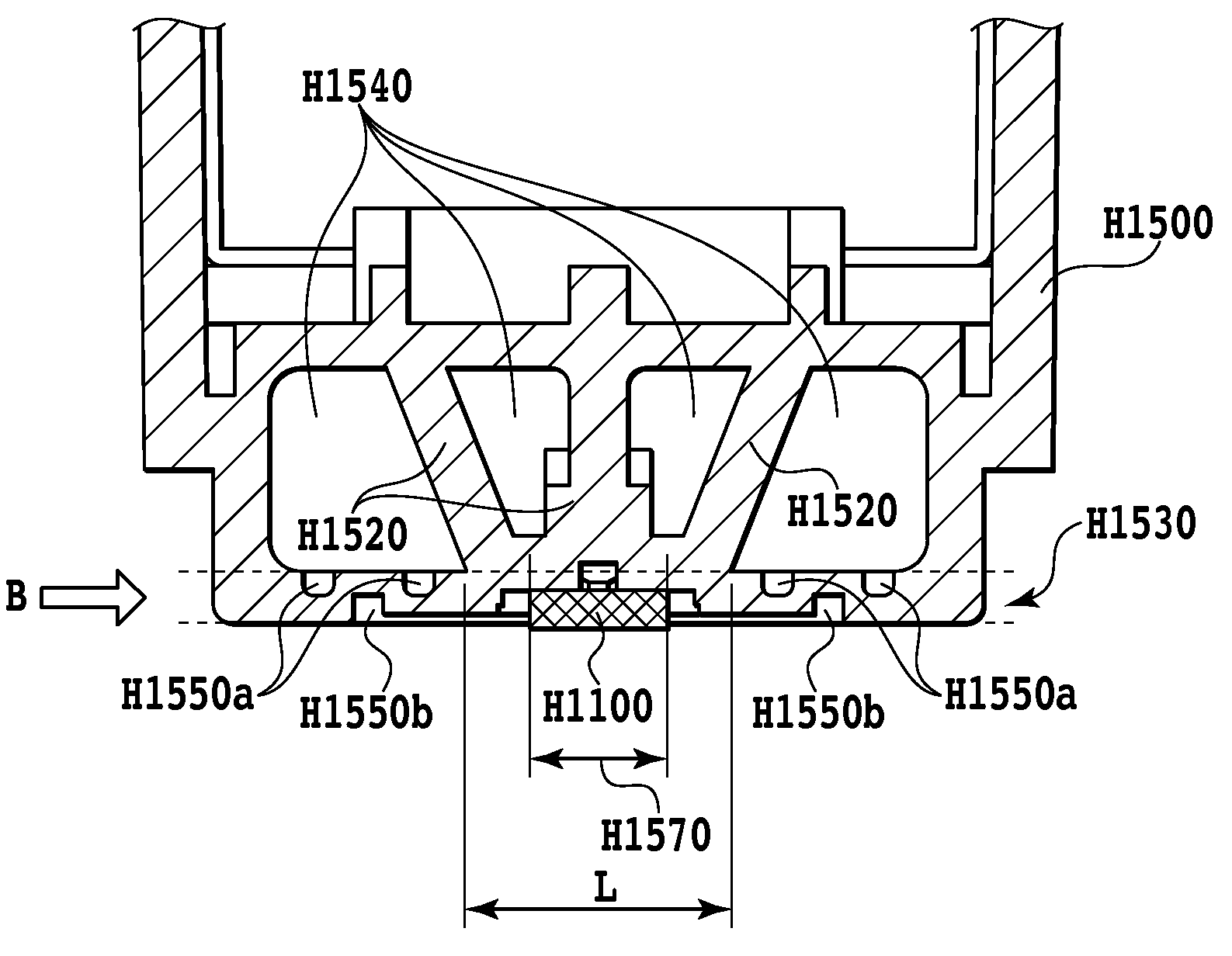
[0059]In the printing head of the first embodiment, the groove H1550a is formed as the concave portion in the rear surface of the region between the printing element substrate and the corner portion R of the major surface of the sheet-shaped portion, of the sheet-shaped portion. However, the present invention is not limited to the concave portion. A structure for absorbing an impact may be formed in the region between the printing element substrate and the corner portion R of the major surface of the sheet-shaped portion, of the sheet-shaped portion holding the printing element substrate.

[0060]FIG. 10 and FIG. 11 are views showing a structure of the first printing head of this embodiment.

[0061]FIG. 10 is an outline view showing only an ink container H1502 and the printing element substrate H1100 among the components constituting the first printing head H1000. A mounting guide H1562 plays a role as a guide for guiding the first printing head H1000 to the mounting position of the carr...

modification embodiment

of the Second Embodiment

[0064]FIG. 12 and FIG. 13 are views showing a structure of the first printing head of an alternative embodiment of the second embodiment.

[0065]FIG. 12 is an outline view showing only an ink container H1503 and the printing element substrate H1100 among the components constituting the first printing head H1000. A mounting guide H1563 plays a role as a guide for guiding the first printing head H1000 to the mounting position of the carriage 102 of the main body of the inkjet printing apparatus.

[0066]FIG. 13 is a cross-sectional view showing a cross section along a XIII-XIII line in FIG. 12. The printing element substrate H1100 is bonded to a bonding region H1573 by adhesive. A cavity portion H1543 is provided for improving the molding stability of the ink container H1500 formed by resin-molding. Then, in a sheet-shaped portion holding the printing element substrate, there is formed a vertical hole H1553 that is a through-hole extending through the major surface ...


PUM


Abstract

A printing head, which can suppress the occurrence of cracks in a printing element substrate, even if accidentally dropped, includes the printing element substrate, an ink flow passage and a sheet-shaped portion comprising a rectangular major surface. A rear surface side of the major surface of the sheet-shaped portion is provided with a space formed separately from the ink flow passage. A surface adjacent to the major surface is provided with an opening of the space formed therein, and the sheet-shaped portion is provided with a concave portion formed on the rear surface side of two regions between the printing element substrate and two corner portions arranged proximate to the opening.

Description

BACKGROUND OF THE INVENTION[0001]1. Field of the Invention[0002]The present invention relates to a printing head. In particular, the present invention relates to a printing head, comprising a support member, being formed of a resin material, to which a printing element substrate of the printing head is bonded.[0003]2. Description of the Related Art[0004]A printing technique using an inkjet method has been known in terms of a low running cost and quiet printing method. In order to provide an inkjet printing apparatus at a lower price, it is effective to achieve a lower cost of a printing head for ejecting ink droplets that accounts for a high proportion of the total cost. A printing element substrate that is a chip for ejecting ink is accurately positioned in the surface of the printing head and bonded and secured thereto. In the printing head that has achieved a lower cost, the bonding surface, to which the printing element substrate is bonded and secured, often comprises a resin me...

Claims


Application Information

Patent Timeline
Patent Type & Authority Patents(United States)
IPC IPC(8): B41J2/135
CPCB41J2/14024B41J2/17553B41J2/1752B41J2002/14362
Inventor SAIKAWA, HIDEOTODA, KYOSUKETSUKUDA, KEIICHIROONO, TAKAYUKI
Owner CANON KK
Why Eureka
Try Eureka