Novel low-frequency inertial vibration feeding machine

A vibrating feeder and inertial technology, which is applied to vibrating conveyors, conveyors, transportation and packaging, etc., can solve the problems of unsatisfactory industrial production material transportation, large basic force, small processing capacity, etc., and increase equipment mobility High efficiency, pure output, and cost-saving effects

Inactive Publication Date: 2016-07-13
XIAN YIMU SOFTWARE TECH
View PDF0 Cites 1 Cited by
  • Summary
  • Abstract
  • Description
  • Claims
  • Application Information

AI Technical Summary

Problems solved by technology

The single-mass conveyor has a simple structure, but it has a large force on the foundation. The double-mass conveyor is generally an electromagnetic vibration conveyor with a small amplitude and

Method used


Image

  • Novel low-frequency inertial vibration feeding machine

Examples


Embodiment 1

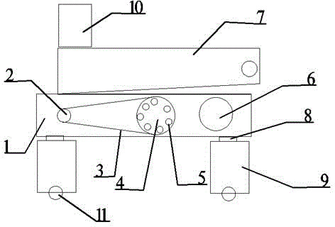
[0019] A new low-frequency inertial vibrating feeder is characterized in that it includes: a frame 1, a driving pulley 2, a V-belt 3, a driven pulley 4, a low-frequency inertial vibration exciter 5, an elastic connection system 6, and a feeding trough 7, Rubber shock-absorbing spring 8, base 9; frame 1 four corners are equipped with rubber shock-absorbing spring 8, and base 9 is connected, and feed trough body 7 is installed on frame 1 by support, rectangular cut rubber spring, and frame 1 The built-in single-axis inertial vibrator 5 is driven to rotate by the driven pulley 4, and the driving pulley 2 and the driven pulley 4 are connected through the V-belt 3; when in use: the vibration source of the tank vibrating feed is a low-frequency inertial vibrator The vibrator is composed of two eccentric shafts and a gear pair. The motor drives the driving shaft through the V-belt, and then the gear on the driving shaft meshes with the driven shaft to rotate. The material flows conti...

Embodiment 2

[0021] Example 2 as figure 1 As shown, it is improved on the basis of Embodiment 1. Its frame 1 is horizontally provided with motor, support, low-frequency inertial vibrator 5, and the motor drives the low-frequency inertia The vibrator 5 rotates. The structure is more compact, the transmission efficiency is higher, the transmission ratio is improved, and the cost is saved.

Embodiment 3

[0023] Example 3 as figure 1 Shown, it is improved on the basis of embodiment 1, and its described feeding trough body 7 is provided with negative pressure dedusting device 10, and this negative pressure dedusting device 10 is film-coated flat dedusting bag type. The use of dust removal equipment for dust removal ensures a clean and hygienic use environment. At the same time, the use of bag dust collectors is conducive to the reuse of accumulated dust and saves costs. At the same time, the film-coated dust bag is used to increase the use time of the dust bag, which can be used for a longer time at one time, reduces the time for replacing the dust bag, and increases work efficiency.


PUM


Abstract

The invention discloses a novel low-frequency inertial vibration feeding machine which comprises a rack, a driving pulley, a triangle belt, a driven pulley, a low-frequency inertial vibration exciter, an elastic connecting system, a feeding groove body, rubber damping springs and a base. Dust removal equipment is adopted for removing dust, and the clean and hygienic use environment is ensured; meanwhile, a bag-type dust remover is used and is beneficial for reutilization of accumulated dust; wheels are arranged, and therefore the feeding machine can be moved at will according to the use requirement; meanwhile, the two front wheels are universal wheels, and therefore the direction can be changed at any time; the feeding groove body arranged in the mode of inclining downwards from front to back is adopted, and fed materials are finer and purer. The technology is mainly applied to crushing and sieving combined equipment in the industry such as metallurgy, coal mine, ore dressing, building materials, chemical engineering and abrasive materials; by means of a low-frequency vibration isolating system, rigidity of the vibration isolating springs changes little, and the novel low-frequency inertial oscillation feeding machine has good vibration isolating performance and is good in conveying performance.

Description

technical field [0001] The invention relates to the field of mechanical applications, and relates to a novel low-frequency inertial vibrating feeder. Background technique [0002] The current conveying equipment is mostly single-mass and double-mass conveyors. The single-mass conveyor has a simple structure, but it has a large force on the foundation. The double-mass conveyor is generally an electromagnetic vibration conveyor with small amplitude and small processing capacity. The structure of the double-mass suspension conveyor is relatively loose, which cannot meet the existing requirements. Conveying of industrial production materials. [0003] Aiming at the deficiencies of the prior art, the present invention designs a new type of low-frequency inertial vibrating feeder, which is mainly used in combined crushing and screening equipment in metallurgy, coal mines, ore dressing, building materials, chemicals, abrasives and other industries. Due to the low-frequency vibrat...

Claims


Application Information

Patent Timeline
IPC IPC(8): B65G27/18
Inventor 赵腾
Owner XIAN YIMU SOFTWARE TECH
Why Eureka
Try Eureka