Device comprising at least a body and a bumper, and robot cleaner comprising such a device

a robot cleaner and body technology, applied in the direction of vacuum cleaners, instruments, domestic applications, etc., can solve problems such as damage to the body

Inactive Publication Date: 2013-06-11
KONINK PHILIPS ELECTRONICS NV
View PDF8 Cites 1 Cited by
  • Summary
  • Abstract
  • Description
  • Claims
  • Application Information

AI Technical Summary

Benefits of technology

[0009]It is an object of the invention to provide a device wherein the movement and guidance of the bumper with respect to the body is realized in a simple manner.
[0021]With such characteristic features of the spring, the bumper will be moved only slightly with respect to the body if, for example, the body accelerates. However, as soon as the bumper hits an object with a force on the bumper that is larger than the predetermined value, the spring exhibits a relatively small stiffness, thus facilitating easy movement of the bumper with respect to the body so that the body is well protected. The bumper is preferably movable with respect to the body through a predetermined distance, with the relatively large stiffness occurring through at least 20 percent of the predetermined distance. In operation, the stiffness must be relatively large through a distance which is as short as possible, up to a certain force level. The stiffness will be small above this force level.
[0023]In this manner, further movement of the body is prevented so that it will not be damaged.

Problems solved by technology

However, when a robot cleaner is moved across a surface, obstacles may be located anywhere so that the direction of impact may be in any direction parallel to the surface across which the robot cleaner is being moved.
Impact in a direction not parallel to the direction in which the bumper is movable with respect to the body may still cause damage to the body.
Such problems do not only occur with robot cleaners but also with other, motor-driven or manually driven devices that are movable across a surface.

Method used


Image

  • Device comprising at least a body and a bumper, and robot cleaner comprising such a device
  • Device comprising at least a body and a bumper, and robot cleaner comprising such a device
  • Device comprising at least a body and a bumper, and robot cleaner comprising such a device

Examples


Embodiment Construction

[0035]In the Figures, identical parts are denoted by the same reference numerals.

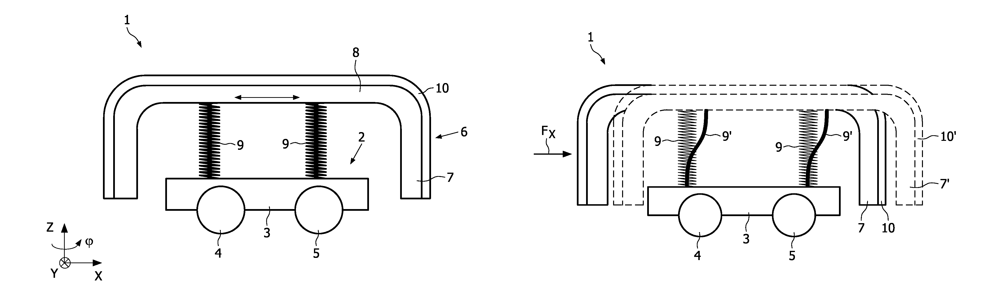
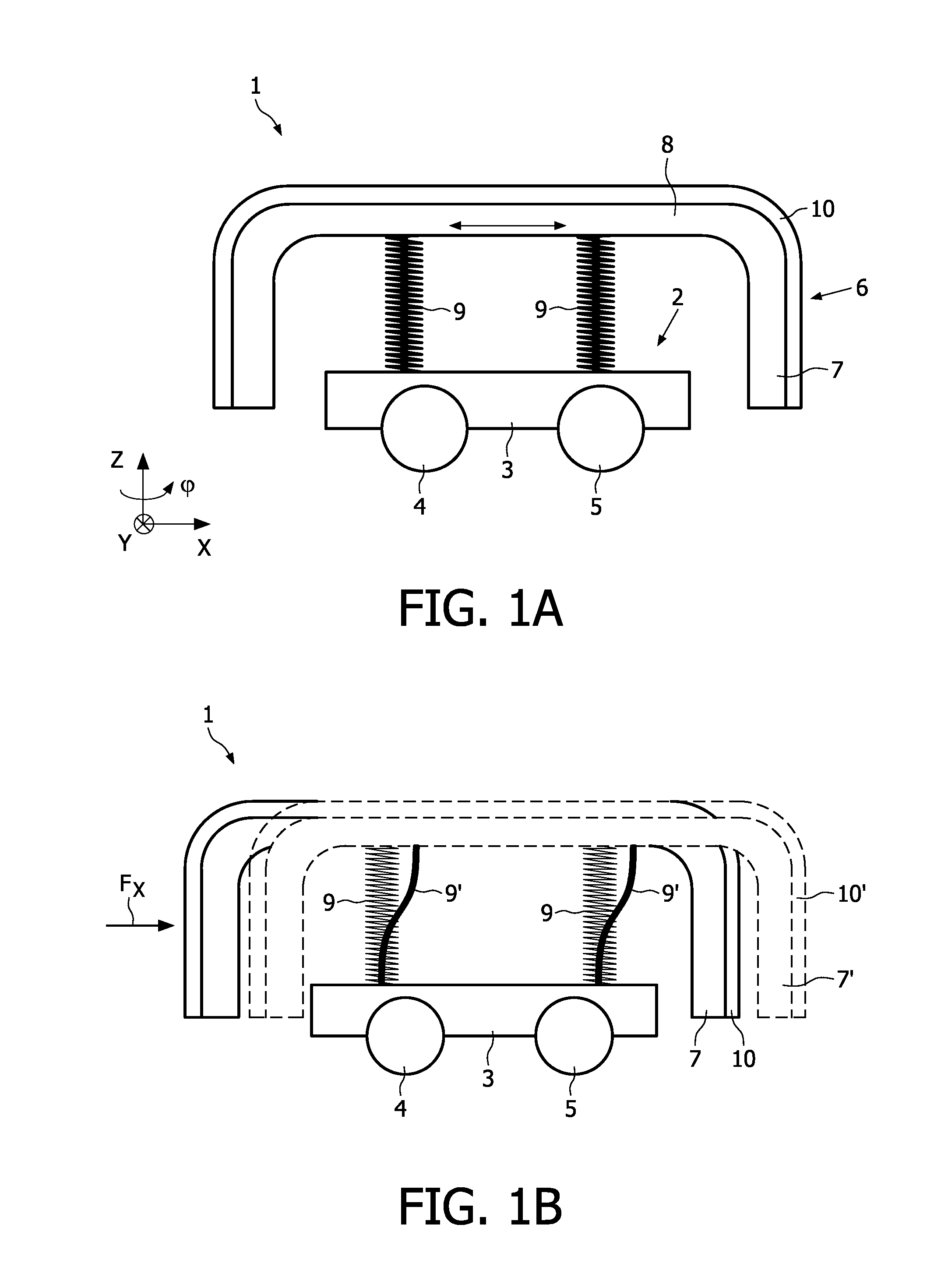
[0036]FIGS. 1A, 1B and 2 show a device 1 according to the invention, comprising a motor-driven body 2 with a housing 3 and two pairs of running wheels 4, 5 located on opposite sides of the housing 3. The device 1 also comprises a bumper 6 which is connected to the body 2 by means of four vertically extending coil springs 9. The bumper 6 comprises a ring-shaped part 7 surrounding the body 2 and being located at a distance from the body 2, which ring-shaped part 7 is connected to a cover part 8 to which the springs 9 are connected. The outer surface of the bumper 6 is provided with a sensor layer 10, the function of which will be described below.

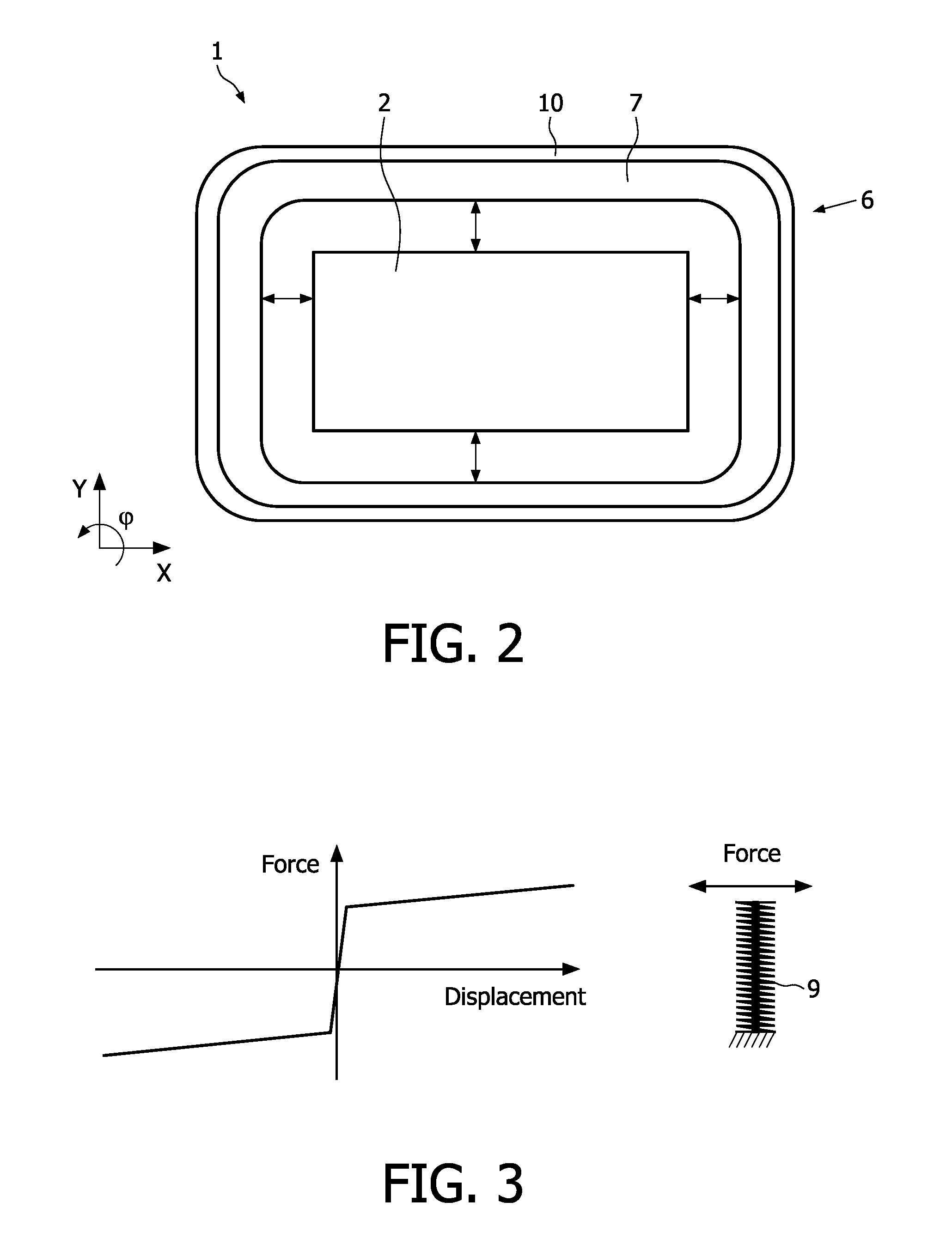
[0037]As can clearly be seen from FIG. 2, the distances between the ring-shaped part 7 and the body 2 on both sides of the body 2 are similar. Also the distances in the X-direction and the Y-direction are similar. However, the distances in the X-direction and the ...


PUM


Abstract

A device (1) comprises at least a body (2) and a bumper (6) which is movably attached to the body so as to protect the body from shock caused by collision with an obstacle during movement of the device across a surface. The bumper is attached to the body by means of at least one spring (9) extending in a direction which is at least substantially perpendicular to the direction into which the bumper is movable with respect to the body. Furthermore, a robot cleaner comprising such a device is provided.

Description

FIELD OF THE INVENTION[0001]The invention relates to a device comprising at least a body and a bumper which is movably attached to the body so as to protect the body from shock caused by collision with an obstacle during movement of the device across a surface.[0002]The invention also relates to a robot cleaner comprising such a device.[0003]The bumper reduces shock to the body but also to the obstacles.BACKGROUND OF THE INVENTION[0004]US2005 / 0021181 discloses a robot cleaner comprising such a device, wherein the body is motor-driven to move the robot cleaner across a surface. A semicircular ring-shaped bumper for mitigating shocks caused by sudden collisions with unexpected obstacles is attached to the body. The bumper is movable with respect to the body in one predetermined direction.[0005]However, when a robot cleaner is moved across a surface, obstacles may be located anywhere so that the direction of impact may be in any direction parallel to the surface across which the robot ...

Claims


Application Information

Patent Timeline
Patent Type & Authority Patents(United States)
IPC IPC(8): A47L5/00
CPCG05D1/0227
Inventor SCHNEIDER, RONALD MAARTENBRUGGERS, JAN WILLEMRIJS, ROBERTUS MATHIJS GERARDUSDEKKERS, JEROEN
Owner KONINK PHILIPS ELECTRONICS NV
Why Eureka
Try Eureka