Shock/vibration dampening

a technology of vibration dampening and vibration, applied in the field of vibration dampening and settling, can solve the problem of increasing the flight distance of an arrow

Active Publication Date: 2012-08-14
SIMS STEVEN C +3
View PDF17 Cites 15 Cited by
  • Summary
  • Abstract
  • Description
  • Claims
  • Application Information

AI Technical Summary

Benefits of technology

[0013]The novel dampeners disclosed herein have an elongated body surrounded by one or more integral, annular vibration dampening elements. When shock and / or vibrations reach the dampener, its components, especially the annular dampening element(s), are so macroscopically and elastically displaced as to very rapidly reduce the time required for the shock and / or vibrations to decay to a harmless, very low level. This removes the factors which keep an arrow from settling, allowing this to occur very quickly and produce the wanted stable and quiet flight.
[0014]Annular dampening elements as described above are typically located toward one end of the dampener body with which they are integrated and dimensioned for a high tolerance slip fit in the shaft in which the dampener is installed (a typical slip fit is one in which the maximum diameter of a vibration dampener is smaller by less than 0.005 inch relative to the inside diameter of an arrow shaft in which the dampener is installed). This leaves an opposite, tip end portion of the dampener body free to wiggle and jiggle when shocks or vibrations are impressed on the dampener, a phenomenon which can significantly increase the effectiveness of the dampener. Also, the high tolerance slip fit provides for decay time modification by sliding friction between the dampening element and the inside wall of the hollow arrow shaft, by the dampener acting to resist motion of the arrow shaft, and by elastic deformation of the elastomeric dampener material.
[0015]The preferred placement of the dampening elements is off-center with respect to an active segment of the device—for example, that segment between a coupling segment at one end of the device and a tip at the opposite end. The preferred off-center locational relationship of the dampening element(s) also enhances the functioning of the dampening device by keeping the device from resonating in phase with the shaft of the arrow in which the dampening device is installed.
[0016]Yet another approach that can be employed to advantage is to employ a set of integral annular elements located along the entire length of the dampener's body component. This increases the number of vibration dampening elements, potentially adding to the decay time modifying ability of a dampener embodying the principles of the present invention.
[0017]A dampener as disclosed herein is installed by slipping (or pressing) it into the hollow shaft of an arrow. This may increase the air pressure in the shaft to a level at which the dampener will pop back out of the shaft when the installation force is removed. This can be avoided by providing an end-to-end axial bore through the dampener.

Problems solved by technology

Furthermore, the minimization of shock and vibration has the potential to decrease drag by minimizing flutter, thereby increasing the flight distance of an arrow.

Method used


Image

  • Shock/vibration dampening
  • Shock/vibration dampening
  • Shock/vibration dampening

Examples


Embodiment Construction

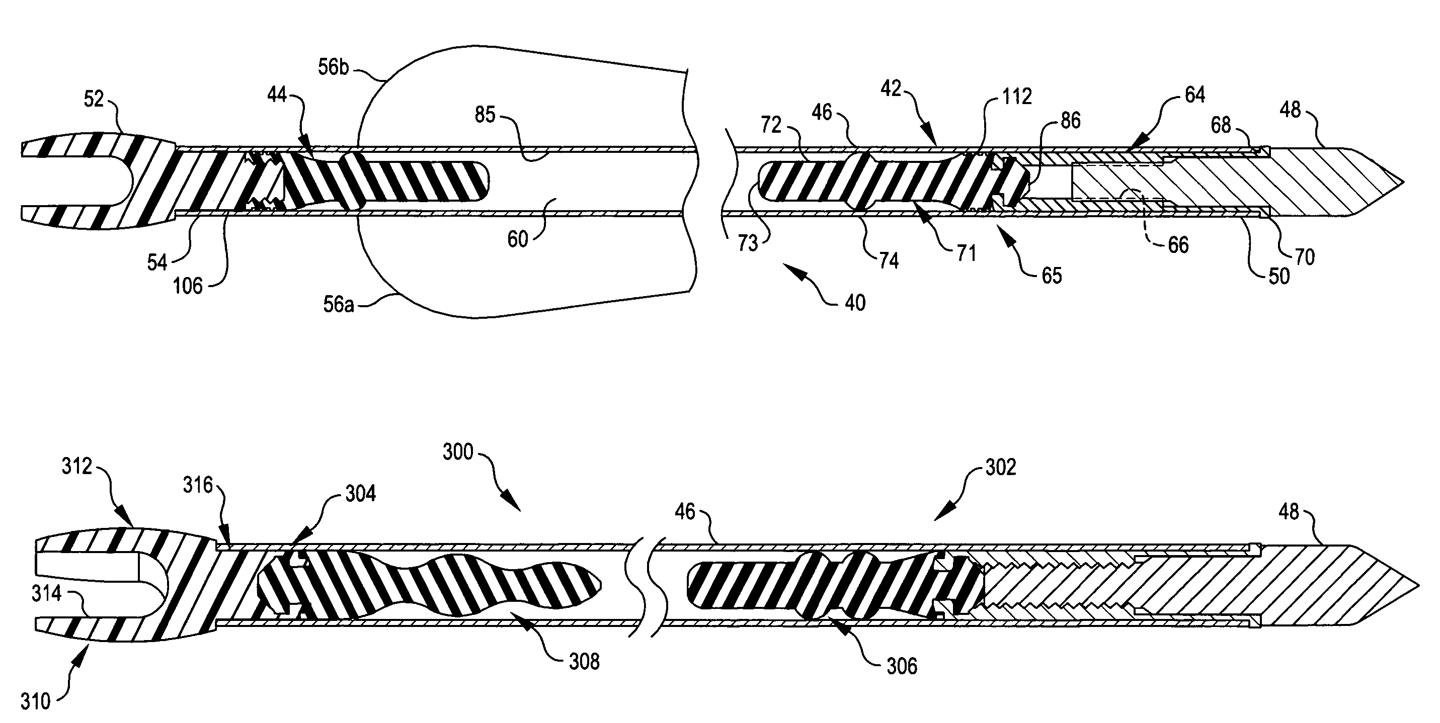
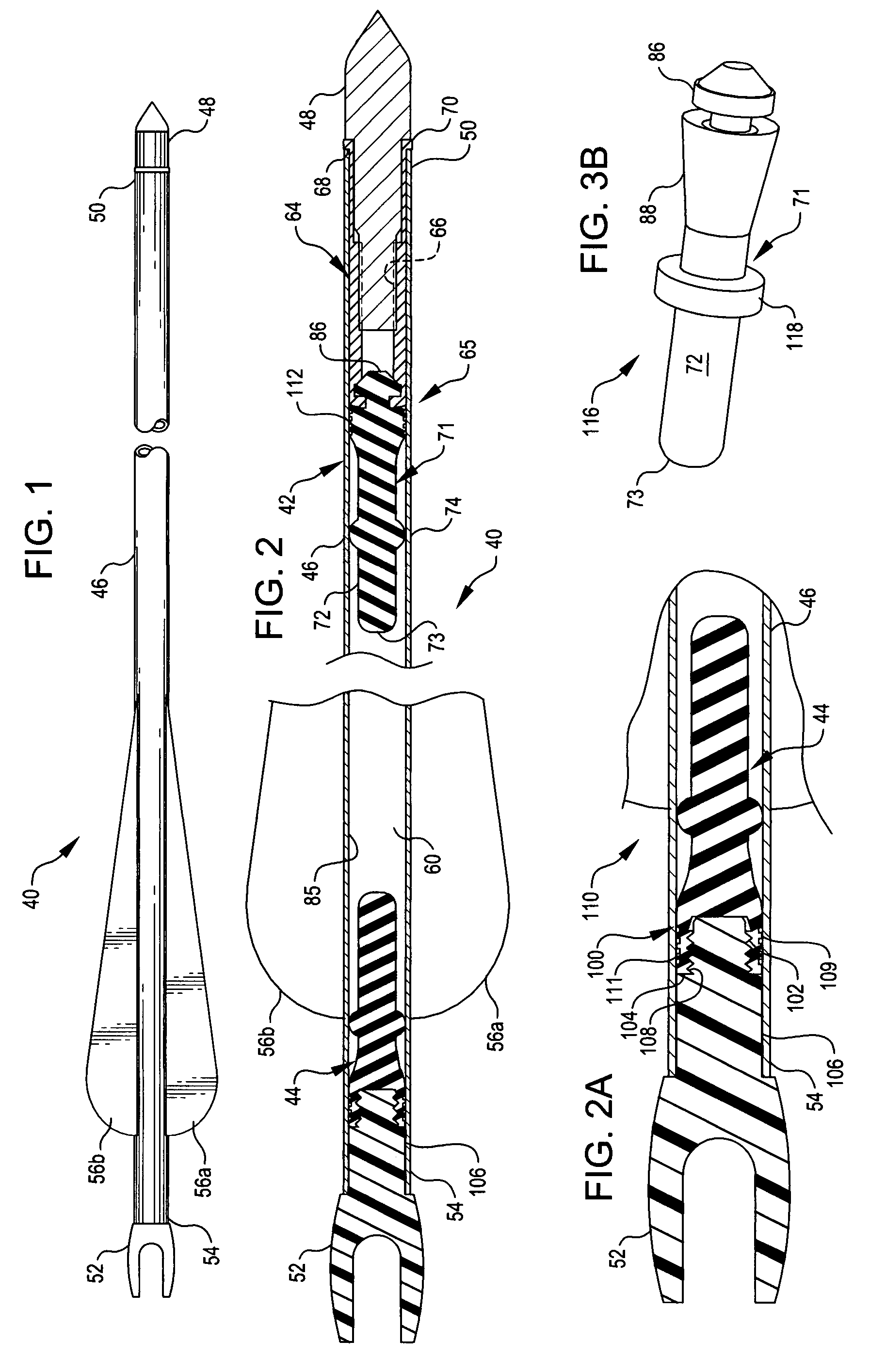
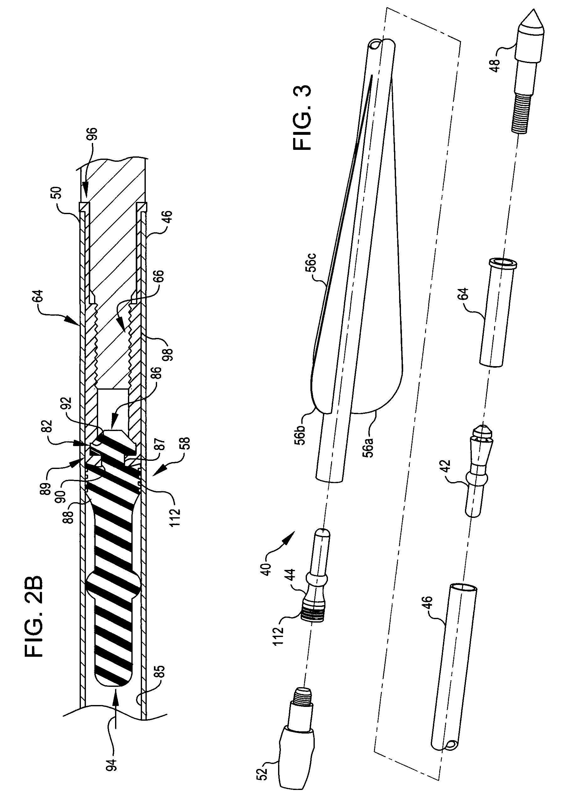
[0050]Referring now to the drawings, FIGS. 1, 2, 2A, 2B, 3, and 3A depict an arrow 40 equipped with: (1) a point end vibration dampener 42, and (2) a nock end vibration dampener 44. Both dampeners are constructed in accord with the principles of the present invention and installed in arrow 40 in accord with those principles.

[0051]Arrow 40 has a hollow shaft 46, an arrow point 48 at the rear end 50 of the shaft, and a nock 52 at the front end 54 of the shaft. Fletches 56a-c of conventional construction are mounted to arrow shaft 46 toward its front end 54.

[0052]Referring now to FIGS. 2, 2A, and 3, point end vibration dampener 42 is dimensioned for a high tolerance slip fit in arrow shaft 46 and is installed in the hollow interior 60 of the shaft toward the rear end 50 of the shaft. Nock end vibration dampener 44 is similarly dimensioned for a high tolerance slip fit in arrow shaft 46 and is installed in the interior 60 of the shaft adjacent the forward, front end 54 of the shaft.

[005...


PUM

PropertyMeasurementUnit
diameteraaaaaaaaaa
pressureaaaaaaaaaa
Settling timeaaaaaaaaaa

Abstract

Vibration dampening devices for arrows are installed in the arrow point end of the arrow shaft or in the nock end of the shaft or in both of those ends. These devices: (a) are fabricated from elastomeric materials; (b) have an elongated core surrounded by one or more annular, vibration dampening elements; and (c) employ decay time modification to attenuate shock and vibration. The devices are assembled in axially aligned relationship to an arrow point insert or arrow nock, and coupling features insure a positive connection between the dampening device and the arrow point insert or nock to which a device is assembled.

Description

CROSS-REFERENCE TO A RELATED APPLICATION[0001]This application is related to and claims the benefit of the 3 May 2006 filing date of provisional patent application No. 60 / 797,257.TECHNICAL FIELD OF THE INVENTION[0002]In one aspect, the present invention relates to the shock / vibration dampening and settling of an arrow as the arrow is shot (or launched) from a bow.[0003]In another aspect, the present invention relates to novel, improved, shock / vibration dampeners which are constructed and configured for installation in the hollow shaft of an arrow.[0004]And, in still another aspect, the present invention relates to arrows which have novel shock / vibration dampeners of the character described in the preceding paragraph and to assemblies of the dampener and an arrow component.DEFINITIONS[0005]An arrow as that term is employed herein is an artifact with an elongated shaft configured and constructed to receive an arrow point at one end and a nock at the opposite end. Arrows as herein defi...

Claims


Application Information

Patent Timeline
Patent Type & Authority Patents(United States)
IPC IPC(8): F42B6/04
CPCF42B6/04Y10T29/49885
Inventor SIMS, STEVEN C.SEIL, JOHNATHAN F.SIMS, GARYWINTERS, GREG
Owner SIMS STEVEN C
Why Eureka
Try Eureka