Radially expandable spinal interbody device and implantation tool

a spinal interbody and radial expansion technology, applied in the field of spinal interbody devices, can solve the problems of undesired abnormal curvature of the spine, disc between vertebrae of a human spine may become damaged, vertebrae may become compressed against a disc or otherwise become damaged, etc., to inhibit or prevent overextension of the linkage

Active Publication Date: 2012-08-14
LIFE SPINE INC
View PDF8 Cites 140 Cited by
  • Summary
  • Abstract
  • Description
  • Claims
  • Application Information

AI Technical Summary

Benefits of technology

[0014]The radially expandable spinal interbody device is formed of arced, pivoting linkages that allow transfiguration from the radially collapsed minimum radial dimensions through and up to the radially expanded maximum radial dimensions once deployed at the implant site (i.e. between adjacent vertebrae). The pivoting linkages have ends with locking features that inhibit or prevent overextension of the linkages. In one form of the locking features, one end of the linkage includes lobes that form a pocket while the other end of the linkage includes a projection that is adapted to be received in the pocket of the lobes of an adjacent linkage.

Problems solved by technology

The disc between vertebrae of a human spine may become damaged due to disease, injury, stress, deterioration because of age or otherwise, or due to a congenital defect.
In some instances vertebrae may become compressed against a disc or otherwise become damaged.
In these and other cases the vertebrae can become too closely spaced anteriorly which causes an undesired abnormal curvature of the spine with respect to lordosis or kyphosis.
Other deformations and / or problems may occur.

Method used


Image

  • Radially expandable spinal interbody device and implantation tool
  • Radially expandable spinal interbody device and implantation tool
  • Radially expandable spinal interbody device and implantation tool

Examples


Embodiment Construction

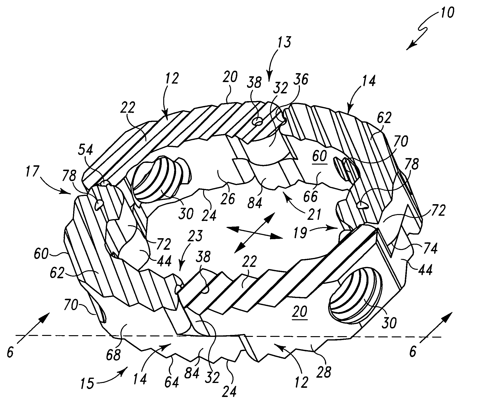
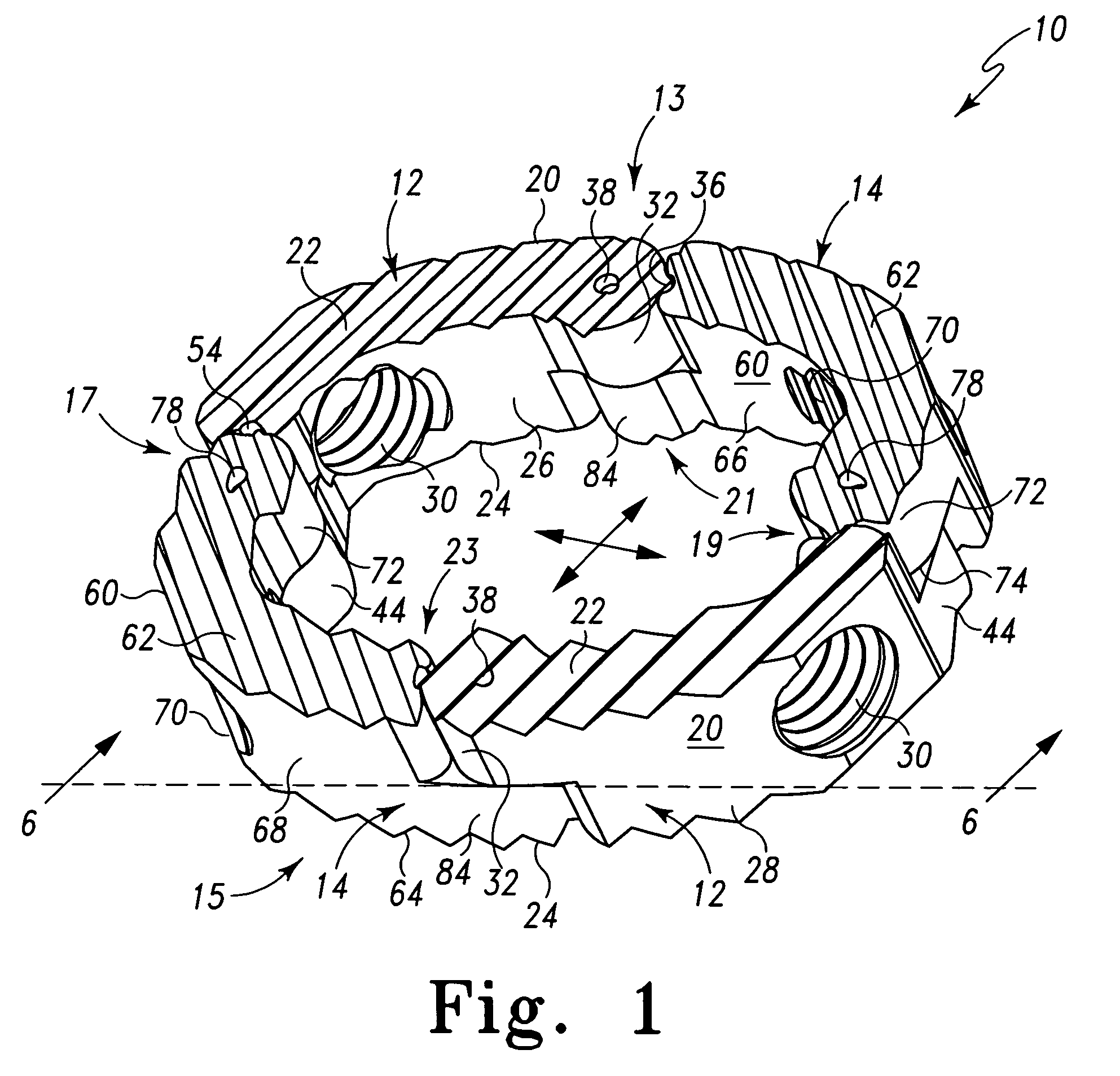
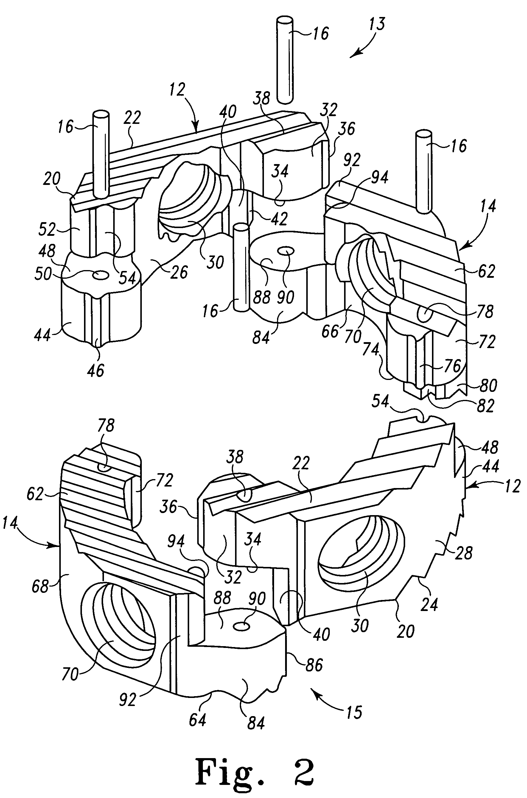
[0031]Referring to the Figures and in particular FIGS. 1-6, there is depicted an exemplary embodiment of a radially expandable interbody device, spinal prosthesis or the like generally designated 10 fashioned in accordance with the present principles. The radially expandable interbody device 10 is configured to be delivered to an implant site in a radially collapsed state or with radially minimal dimensions 200 (see, e.g., FIG. 8) and then radially expanded or with radially maximum dimensions 300 at the implant site (see, e.g., FIG. 9) hence the term expandable or dynamic. In this manner, the radially expandable interbody device 10 may be delivered to the implant site through a small delivery area when in the radially collapsed state and then easily radially expanded when implanted. The radially expandable interbody device 10 may be fashioned from a biocompatible material such as titanium, a titanium alloy, stainless steel, other metal, polymer, composite, ceramic and / or any combina...


PUM


Abstract

A radially expandable spinal interbody device for implantation between adjacent vertebrae of a spine is deliverable to an implant area in a radially collapsed state having minimum radial dimensions and once positioned is then radially expandable through and up to maximum radial dimensions. The expanded radially expandable spinal interbody device is configured to closely mimic the anatomical configuration of a vertebral face. The radially expandable spinal interbody device is formed of arced, pivoting linkages that allow transfiguration from the radially collapsed minimum radial dimensions through and up to the radially expanded maximum radial dimensions once deployed at the implant site (i.e. between adjacent vertebrae). The pivoting linkages have ends with locking features that inhibit or prevent overextension of the linkages. In one form of the locking features, one end of the linkage includes lobes that form a pocket while the other end of the linkage includes a projection that is adapted to be received in the pocket of the lobes of an adjacent linkage. A kit is also provided including a tool for the implantation and deployment of the spinal interbody device into an intervertebral space.

Description

RELATED APPLICATIONS[0001]This patent application claims the benefit of and / or priority to U.S. Provisional Patent Application Ser. No. 60 / 920,766 filed Mar. 29, 2007, entitled “Expandable Spinal Interbody Device and Implantation Tool” the entire contents of which is specifically incorporated herein by reference.BACKGROUND OF THE INVENTION[0002]1. Field of the Invention[0003]The present invention relates to spinal interbody devices for implantation between a pair of adjacent vertebrae for providing support to the adjacent vertebrae for fusion thereof and, more particularly, to expandable interbody devices for implantation between a pair of adjacent vertebrae for providing support to the adjacent vertebrae for fusion thereof.[0004]2. Background Information[0005]The disc between vertebrae of a human spine may become damaged due to disease, injury, stress, deterioration because of age or otherwise, or due to a congenital defect. In some instances vertebrae may become compressed against...

Claims


Application Information

Patent Timeline
Patent Type & Authority Patents(United States)
IPC IPC(8): A61F2/44
CPCA61F2/4465A61F2/4611A61F2/442A61F2/4601A61F2002/2817A61F2002/2835A61F2002/3008A61F2002/30126A61F2002/302A61F2002/30471A61F2002/30579A61F2002/30841A61F2002/30904A61F2002/4415A61F2002/4627A61F2002/4629A61F2220/0091A61F2230/0008A61F2230/0065A61F2250/0098A61F2310/00017A61F2310/00023A61F2310/00179A61F2002/30365A61F2002/30367A61F2002/30545
Inventor BUTLER, MICHAEL S.MILELLA, JR., MICHAEL J.
Owner LIFE SPINE INC
Why Eureka
Try Eureka