
Flexible-circuit-board cable with positioning structure for insertion

a flexible circuit board and positioning structure technology, applied in the direction of printed circuit manufacturing, printed circuit aspects, cross-talk/noise/interference reduction, etc., can solve the problems of loss of stable electrical connection between the connector and loss of signal transmission between systems, and affecting the force that the connector applies to hold the flexible circuit board cable, etc., to achieve excellent shielding effect, easy loosing and separation, and eliminating increased costs

Active Publication Date: 2012-08-14
ADVANCED FLEXIBLE CIRCUITS
View PDF7 Cites 12 Cited by
  • Summary
  • Abstract
  • Description
  • Claims
  • Application Information

AI Technical Summary

Benefits of technology

"The present invention provides a flexible-circuit-board cable with a positioning structure that can be securely retained in an electrical connector and effectively eliminate external electromagnetic interference. The cable has a connection zone with a raised projection section that engages with the connector to securely position the cable. The cable also has shielding layers that conduct external electromagnetic interference through the end of the cable to the circuit board, providing excellent shielding. The cable can be easily manufactured using existing techniques without additional manufacturing costs."

Problems solved by technology

However, since the upper surface of the flexible-circuit-board cable and the undersurface of the hold-down cover of the connector are both planar, the resulting mating force therebetween is generally insufficient, and this affects the force that the connector applies to hold the flexible-circuit-board cable.
Consequently, the flexible-circuit-board cable may easily get loosened and separated from the connector, leading to loss of stable electrical connection between the connector and the flexible-circuit-board cable and loss of signal transmission between systems.
Although connectors that overcome such a problem are available in the market, yet they are complicated in structure and require a tedious manufacturing process.
However, since the surfaces of the conductors of the flexible-circuit-board cable exhibit a planar configuration, which prevents the conductive terminals of the connector that are to be put in contact therewith from being correctly and securely positioned on the conductors.
Again, this makes the flexible-circuit-board cable easily loosened and separated from the connector, and such separation disables transmission of signals.
Further, the conventional connector of this kind is not capable of effectively eliminating external electromagnetic interference.
Consequently, signal transmission between systems often suffers noise interference, which adversely affects the quality of signals.

Method used


Image

  • Flexible-circuit-board cable with positioning structure for insertion
  • Flexible-circuit-board cable with positioning structure for insertion
  • Flexible-circuit-board cable with positioning structure for insertion

Examples


Embodiment Construction

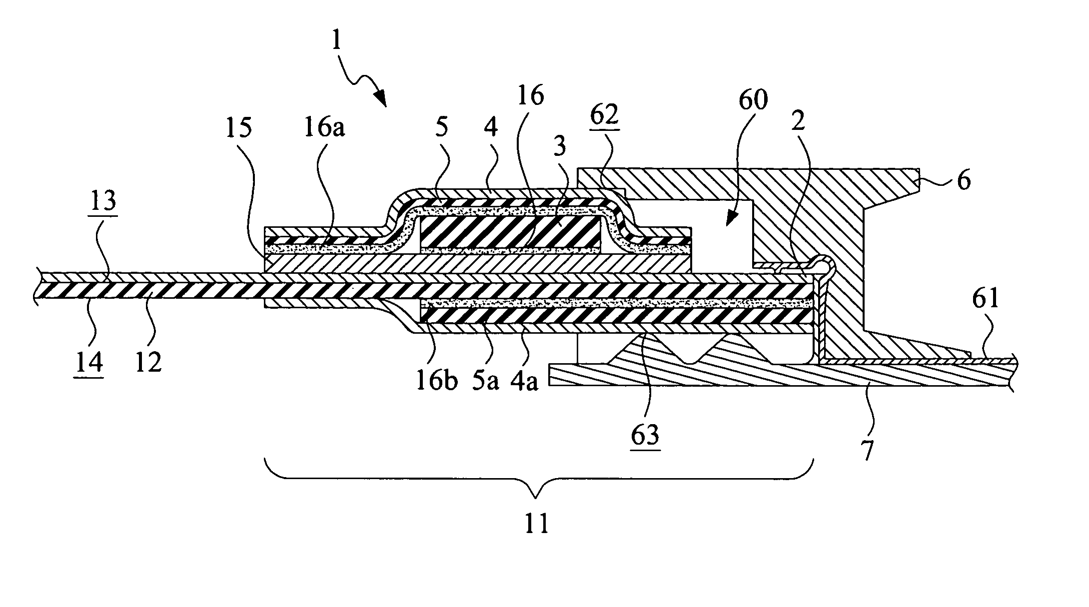
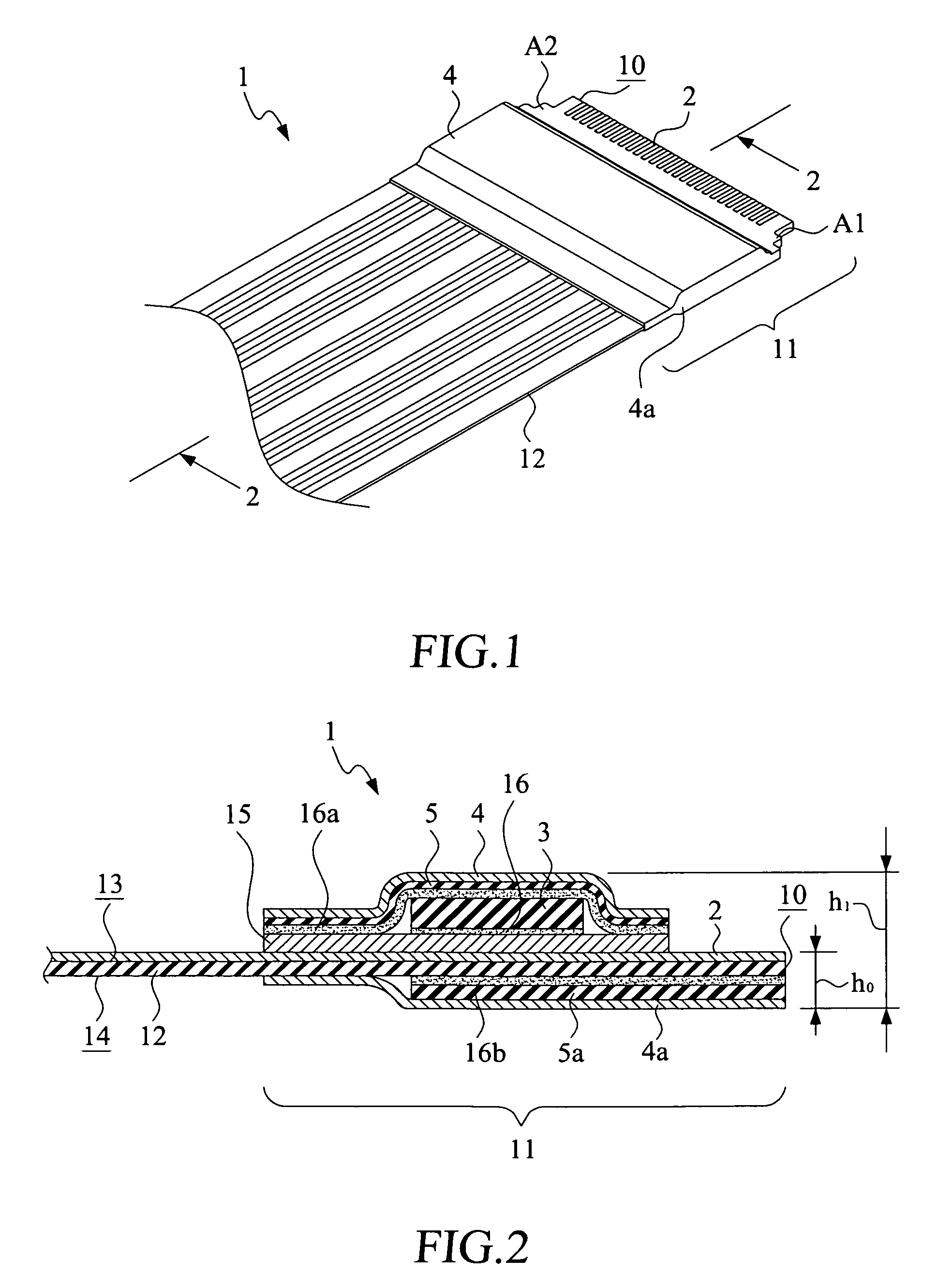
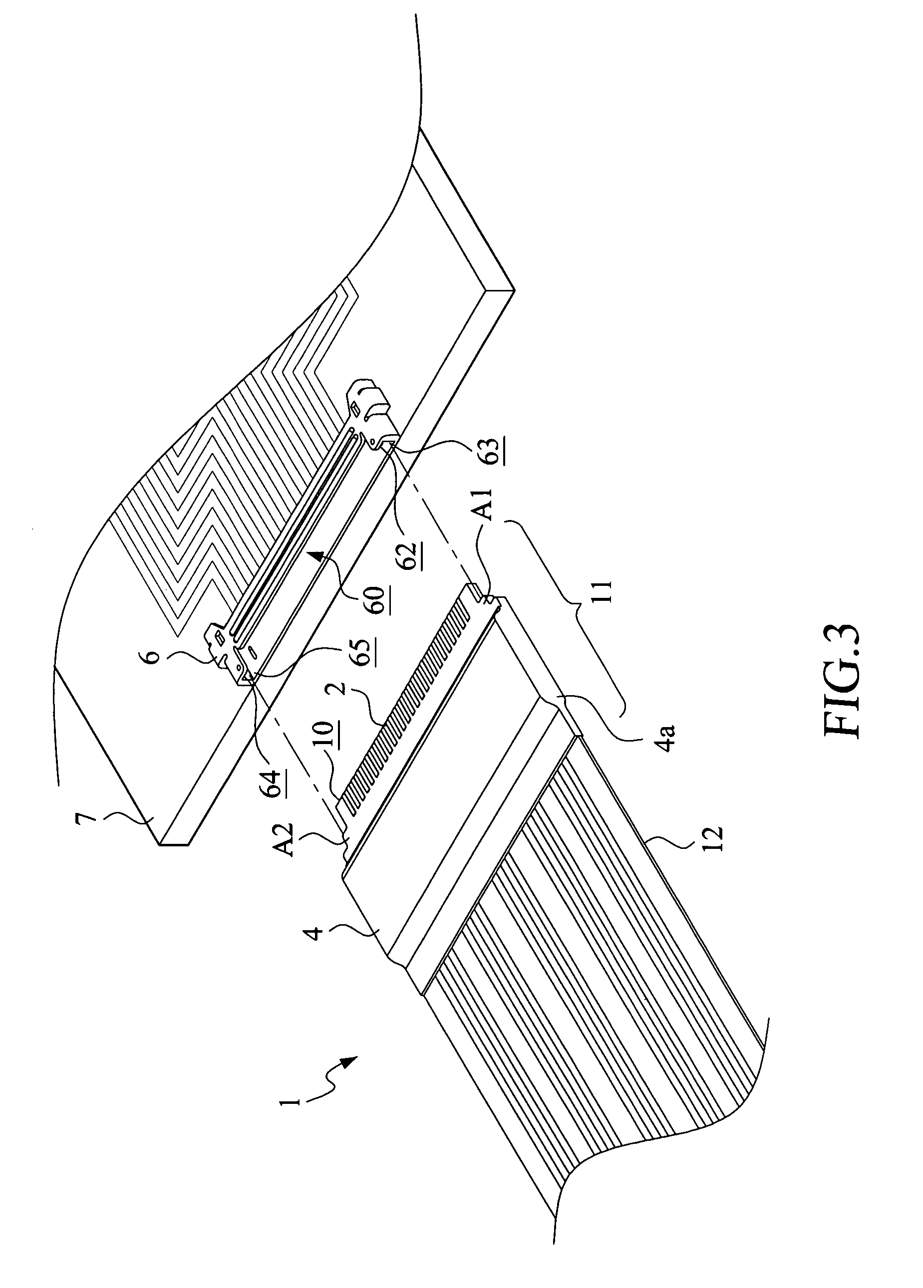
[0023]With reference to the drawings and in particular to FIGS. 1 and 2, of which FIG. 1 shows a perspective view of a first embodiment in accordance with the present invention and FIG. 2 shows a cross-sectional view taken along line 2-2 of FIG. 1, the present invention provides a flexible-circuit-board cable 1 that has a positioning structure for insertion operation. The flexible-circuit-board cable 1 has a free end 10 that defines a connection zone 11. The flexible-circuit-board cable 1 comprises a flexible circuit substrate 12. The connection zone 11 is defined in the flexible circuit substrate 12 and has a first surface 13 and a second surface 14. The first surface 13 is provided thereon with a plurality of conductive contacts 2. The first surface 13 is further covered with an insulation layer 15. Bonded atop the insulation layer 15 with an adhesive layer 16 is at least one projection section 3.

[0024]As shown in the drawings, the projection section 3 is raised above a reference ...


PUM


Abstract

Provided is a flexible-circuit-board cable having a positioning structure. A connection zone is defined in a free end of the flexible-circuit-board cable and is provided with a plurality of conductive contacts. The connection zone has a first surface on which at least one projection section is formed and a second surface. A shielding layer overlaps the projection section and a portion of the first surface. The second surface of the connection zone is also bonded to a shielding layer. When the connection zone of the flexible-circuit-board cable is inserted into an insertion space defined in a connector, the first and second local zones of the connection zone formed by the shielding layers and the projection section are put into engagement with and thus positioned and retained by walls on opposite sides of the insertion space of the connector to thereby fix within the connector.

Description

FIELD OF THE INVENTION[0001]The present invention relates to a flat cable formed of a flexible circuit board, and in particular to a flexible-circuit-board cable having a positioning structure for insertion operation thereof.BACKGROUND OF THE INVENTION[0002]It is known that an electrical connector establishes electrical connection between electrical cables, circuit boards, and other electrical circuit components through physical engagement. The electrical connector finds wide applications in various electrical / electronic products, such as notebook computers and personal digital assistants (PDAs).[0003]A regular electrical connector is often fixed to a circuit board through soldering so that connection terminals of the connector are set in electrical engagement with contacts of circuit layout on the circuit board to establish electrical connection therebetween. In some applications, the electrical connector may also play a role of retaining another circuit component, such as retainin...

Claims


Application Information

Patent Timeline
Patent Type & Authority Patents(United States)
IPC IPC(8): H05K1/00
CPCH05K1/118H05K1/0218H05K2203/167H05K2201/2036H05K2201/10189
Inventor CHUO, CHIH-HENGSU, KUO-FU
Owner ADVANCED FLEXIBLE CIRCUITS
Learn More