Transmission-line transformer

Active Publication Date: 2012-08-21
WERLATONE INC
View PDF27 Cites 8 Cited by
  • Summary
  • Abstract
  • Description
  • Claims
  • Application Information

AI Technical Summary

Problems solved by technology

Often these antennas have an input impedance that does not match the desired transmitter or receiver with which it is used.

Method used


Image

  • Transmission-line transformer
  • Transmission-line transformer
  • Transmission-line transformer

Examples


Embodiment Construction

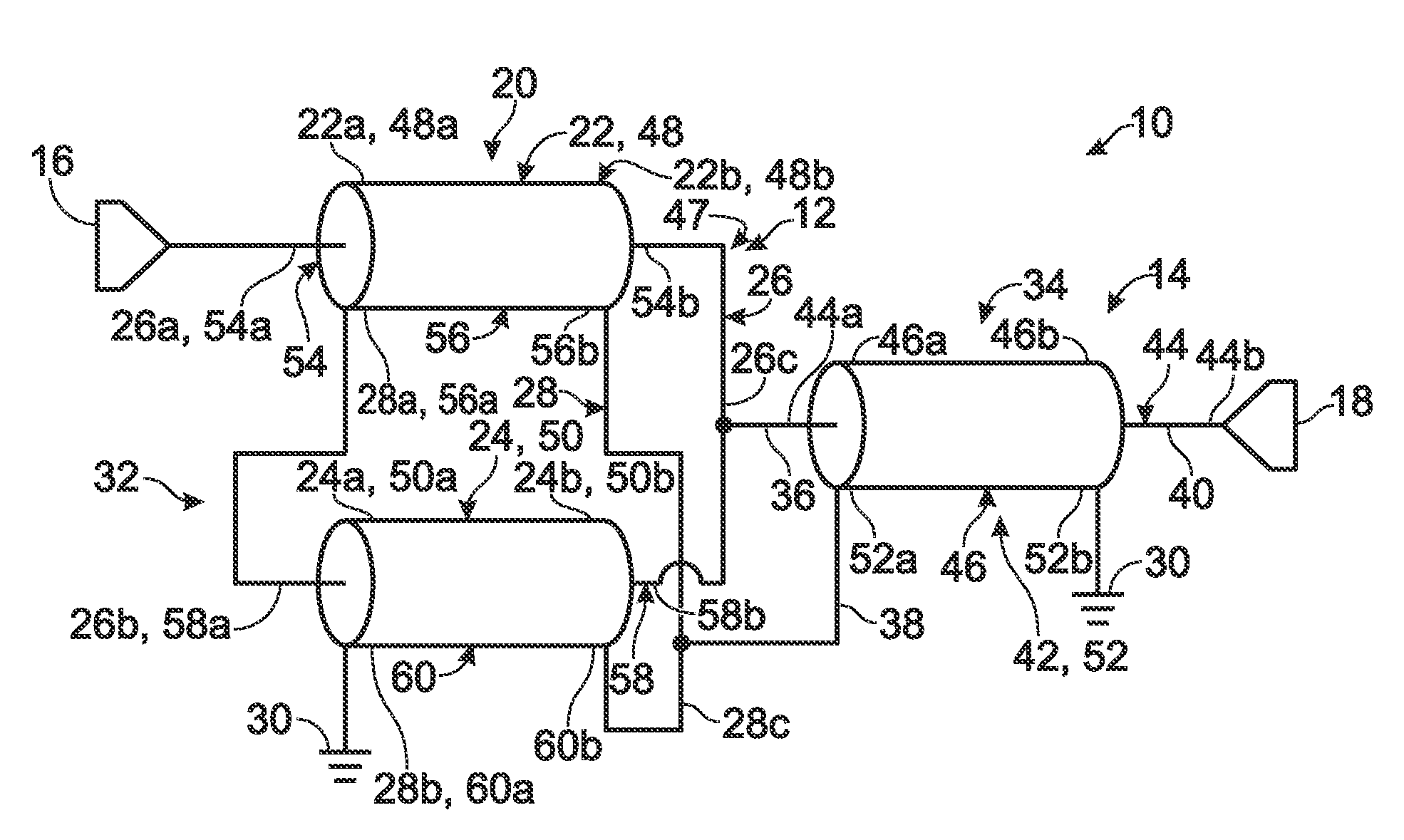
[0016]A first example of a transmission-line transformer is shown generally at 10 in FIG. 1. In this example, transmission-line transformer 10 includes a transmission-line assembly 12 and a balun assembly 14 extending between a first port 16 and a second port 18. As used in this description, ports are places on conductors where variables or characteristics of a circuit may be observed or measured. Ports may or may not be places of access to the circuit where energy may be supplied (input) or withdrawn (output), depending on the particular structure and application of the circuit. Either one of ports 16 and 18 may be an input port and the other an output port, depending on the particular application.

[0017]Transmission-line assembly 12 may include a transmission line 20 that may include a plurality of transmission-line sections, such as transmission-line sections 22 and 24. Although represented as separate sections of coaxial transmission lines, the sections may be formed as a continu...


PUM


Abstract

An example of a transmission-line transformer may include a transmission-line assembly and a balun assembly. The transmission-line assembly may include first and second conductors forming at least first and second transmission-line sections. The transmission-line assembly may provide a signal path through the first conductor and second conductor in series to a circuit ground. Balanced lines of the balun assembly may be connected to respective intermediate points on the first and second conductors between the first and second transmission-line sections. The transmission-line transformer may provide a signal path between a first end of the first conductor of the transmission-line assembly and the unbalanced line of the balun assembly.

Description

RELATED APPLICATIONS[0001]This application claims the benefit of U.S. Provisional Application No. 61 / 247,308, filed Sep. 30, 2009, and incorporated herein by reference in its entirety for all purposes.BACKGROUND[0002]For certain applications, there is a need for a broadband, high power communication system. For example, in military applications a broad bandwidth is required for secure spread spectrum communication and high power is required for long range. High power broadband communication systems require high power broadband antennas. Often these antennas have an input impedance that does not match the desired transmitter or receiver with which it is used. In such circumstances, impedance transformers can be used to transform the impedance of the antenna to the impedance of the transmitter or receiver.[0003]Transmission-line transformers may be used for matching networks for antennas and amplifiers operating at radio frequencies, such as frequencies in the HF and VHF bands. They a...

Claims


Application Information

Patent Timeline
Patent Type & Authority Patents(United States)
IPC IPC(8): H03H7/42H01P3/02
CPCH01P5/10
Inventor PODELL, ALLEN F.
Owner WERLATONE INC
Why Eureka
Try Eureka