This helps you quickly interpret patents by identifying the three key elements:
Problems solved by technology
Method used
Benefits of technology
Problems solved by technology
The wiring installed in buildings may need to be substantial enough to carry a relatively large amount of current because the type and number of devices that may ultimately be connected to any one circuit may be unknown at the time of installation.
Method used
Image
Click on the blue label to locate the original text in one second.
Reading with bidirectional positioning of images and text.
Examples
Embodiment Construction
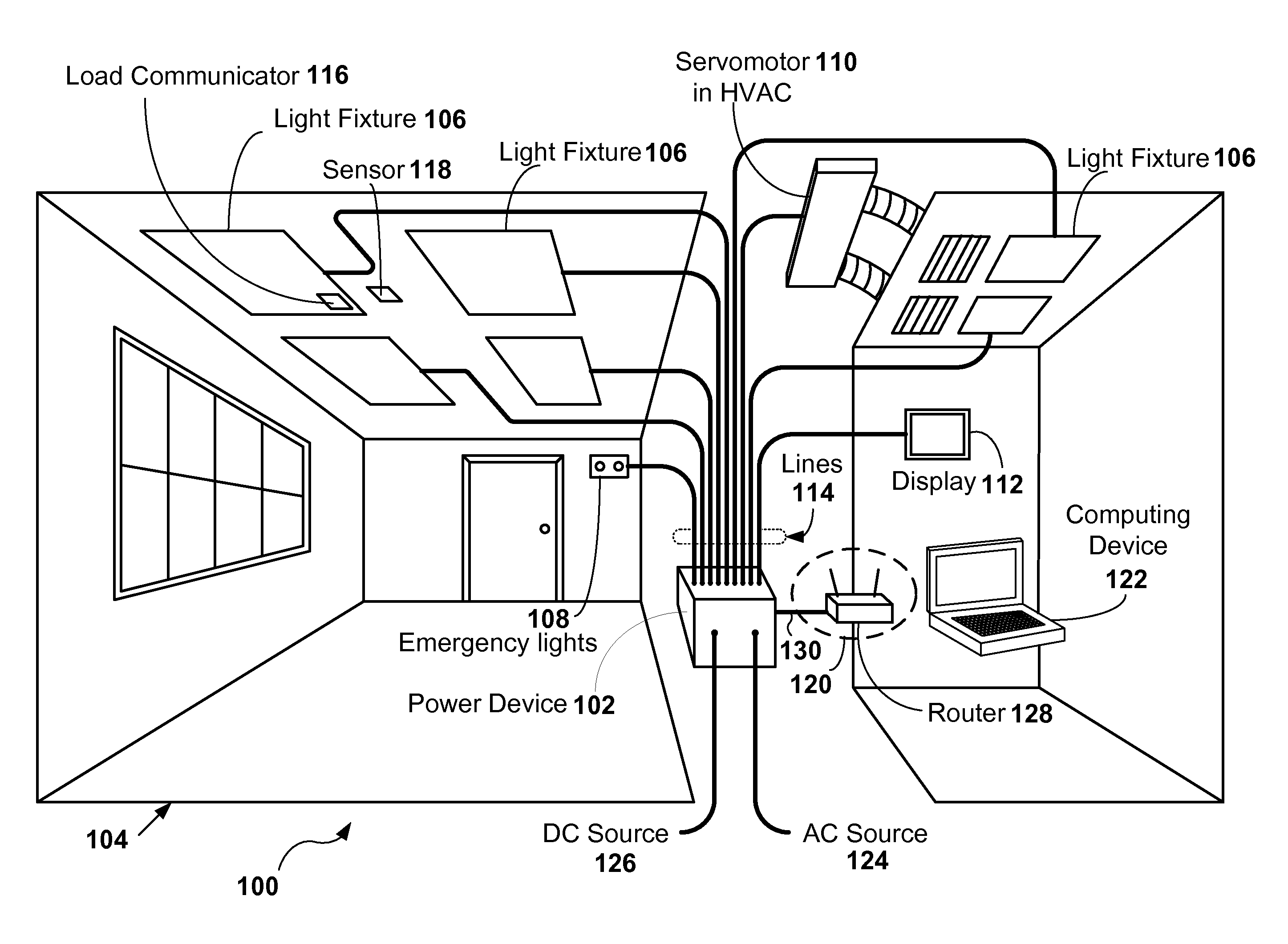
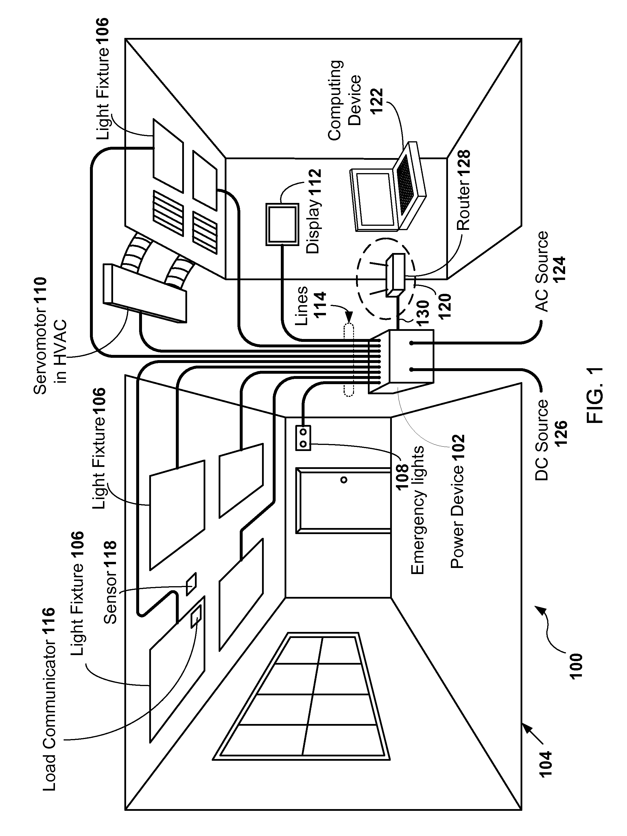
[0015]A power device may provide a DC power signal over multiple lines to multiple load devices. The load devices may include light fixtures, sensors, motors, display screens, or any other device that consumes electrical power. The load devices may be powered by the DC power signal. Each one of the load devices may receive the DC power signal over a different one of the lines than the other load devices. The DC power signal of one or more of the lines may be used by multiple load devices. The DC power signal may be pulse-width modulated (PWM) signal.
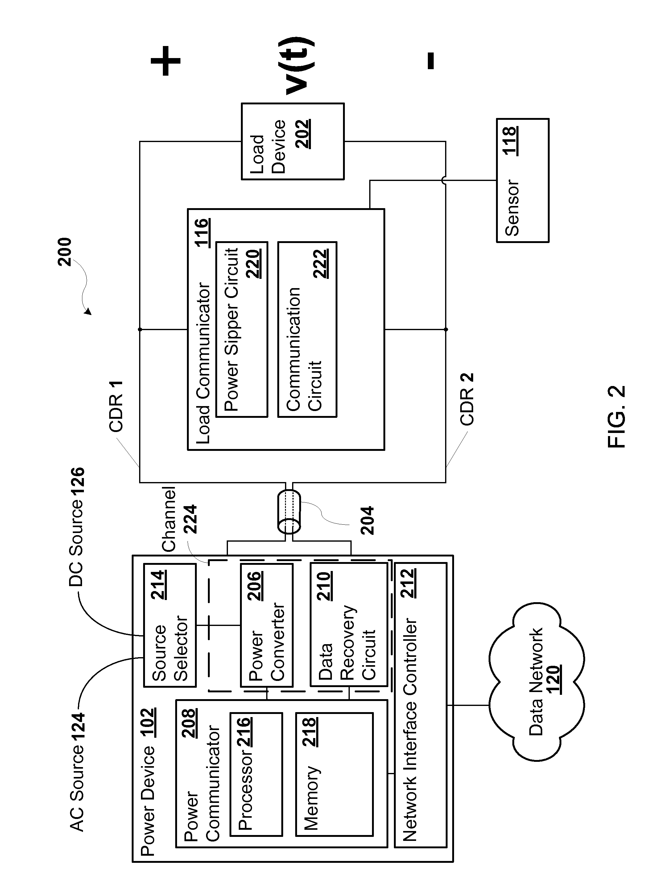
[0016]Each one of the load devices may include a load communicator. Alternatively or in addition, the load communicators may be electrically coupled to the lines at or near the load devices. The load communicator may be any circuit that transmits data to or receives data from the power device via the same conductor or conductors that propagate the DC power signal over the line to the load device. For example, each one of the lines may in...
PUM
Abstract
A power device may include channels coupled to conductors in lines, where each one of the channels is coupled to a different one of the lines than the other channels and where the channels deliver direct current power signals over the conductors to the load devices. Each one of the load devices may be powered by a different one of the direct current power signals. The power device may include a power communicator that communicates with the load devices over the conductors that propagate the direct current power signals. The power communicator may determine a target power level for the load devices based on the communication over the conductors. The load device may adjust an amount of power in the direct current power signals in order to match the target power level.
Description
[0001]This application is a continuation-in-part (CIP) of, and claims priority under U.S.C. §120 to, U.S. patent application Ser. No. 12 / 389,868, entitled “TRANSMISSION OF POWER AND DATA WITH FREQUENCY MODULATION,” filed Feb. 20, 2009, the entire contents of which are hereby incorporated herein by reference, U.S. patent application Ser. No. 12 / 536,231, entitled “DIGITAL SWITCH COMMUNICATION,” filed Aug. 5, 2009, the entire contents of which are hereby incorporated herein by reference, and U.S. patent application Ser. No. 12 / 753,376, entitled “HYBRID FLUORESCENT LIGHT CONTROLLER,” filed Apr. 2, 2010, the entire contents of which are hereby incorporated herein by reference. This application claims priority under 35 U.S.C. §119(e) to U.S. Provisional Application No. 61 / 330,536, “SMART POWER DEVICE” filed May 3, 2010, the entire contents of which are hereby incorporated herein by reference.BACKGROUND[0002]1. Technical Field[0003]This application relates to transmission of power and, in ...
Claims
Application Information
Patent Timeline
Application Date:The date an application was filed.
Publication Date:The date a patent or application was officially published.
First Publication Date:The earliest publication date of a patent with the same application number.
Issue Date:Publication date of the patent grant document.
PCT Entry Date:The Entry date of PCT National Phase.
Estimated Expiry Date:The statutory expiry date of a patent right according to the Patent Law, and it is the longest term of protection that the patent right can achieve without the termination of the patent right due to other reasons(Term extension factor has been taken into account ).
Invalid Date:Actual expiry date is based on effective date or publication date of legal transaction data of invalid patent.