Magnetic head suspension for supporting piezoelectric elements in a non-facing manner relative to suspension structure

a piezoelectric element and non-facing technology, applied in the field of magnetic head suspension, can solve the problems of bending deformation of the piezoelectric element paired, unstable floating movement of the magnetic head slider, etc., and achieve the effect of preventing or reducing a bending deformation of the piezoelectric elemen

Active Publication Date: 2012-08-21
SANCALL CORP
View PDF6 Cites 72 Cited by
  • Summary
  • Abstract
  • Description
  • Claims
  • Application Information

AI Technical Summary

Benefits of technology

[0025]The present invention has been achieved in view of the above conventional art, and it is a object thereof to provide a magnetic head suspension that enables coarse motion of a magnetic head slider by a main actuator as well as micro motion of the magnetic head slider by piezoelectric elements, the magnetic head suspension capable of effectively preventing or reducing a bending deformation of the piezoelectric element in a direction orthogonal to a disk surface when the piezoelectric element is expanded and contracted, thereby stabilizing floating movement of the magnetic head slider at the time of being moved in the seek direction by the piezoelectric elements.
[0029]The thus configured magnetic head suspension according to the present invention makes it possible to effectively prevent or reduce a bending deformation of the paired piezoelectric elements in a direction orthogonal to the disk surface when the paired piezoelectric elements are expanded and contracted, thereby stabilizing floating movement of the magnetic head slider at the time of being moved in the seek direction by the paired piezoelectric elements.

Problems solved by technology

However, each of the magnetic head suspensions disclosed in the prior art documents 1-3 has a problem that the paired piezoelectric elements are likely to be deformed in a bending manner in the thickness direction when being expanded and contracted.
As a result, floating movement of the magnetic head slider is become unstable when it is moved in the seek direction.
As a result, the piezoelectric element is deformed in a bending manner in the direction orthogonal to the disk surface when being expanded or contracted, whereby floating movement of the magnetic head slider is become unstable when it is moved in the seek direction by the piezoelectric elements.

Method used


Image

  • Magnetic head suspension for supporting piezoelectric elements in a non-facing manner relative to suspension structure
  • Magnetic head suspension for supporting piezoelectric elements in a non-facing manner relative to suspension structure
  • Magnetic head suspension for supporting piezoelectric elements in a non-facing manner relative to suspension structure

Examples


first embodiment

[0057]Hereinafter, one preferred embodiment of a magnetic head suspension according to the present invention will be described, with reference to the attached drawings.

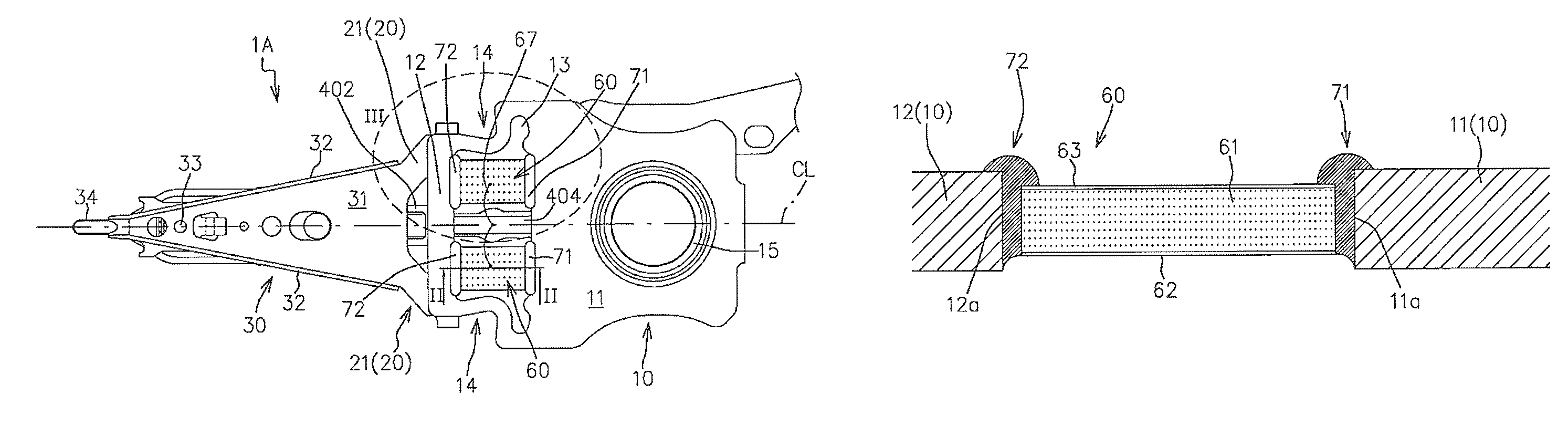
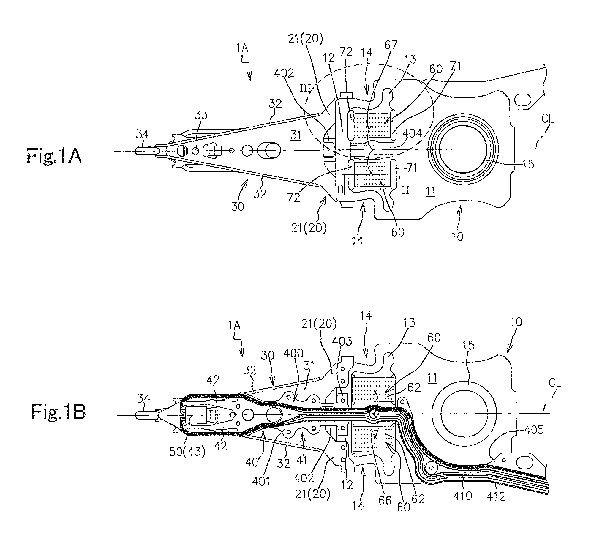
[0058]FIGS. 1A and 1B are a top view (a plan view as viewed from a side opposite from a disk surface) and a bottom view (a bottom plan view as viewed from a side close to the disk surface) of a magnetic head suspension 1A according to the present embodiment, respectively. FIG. 1B indicates welding points with using small circles.

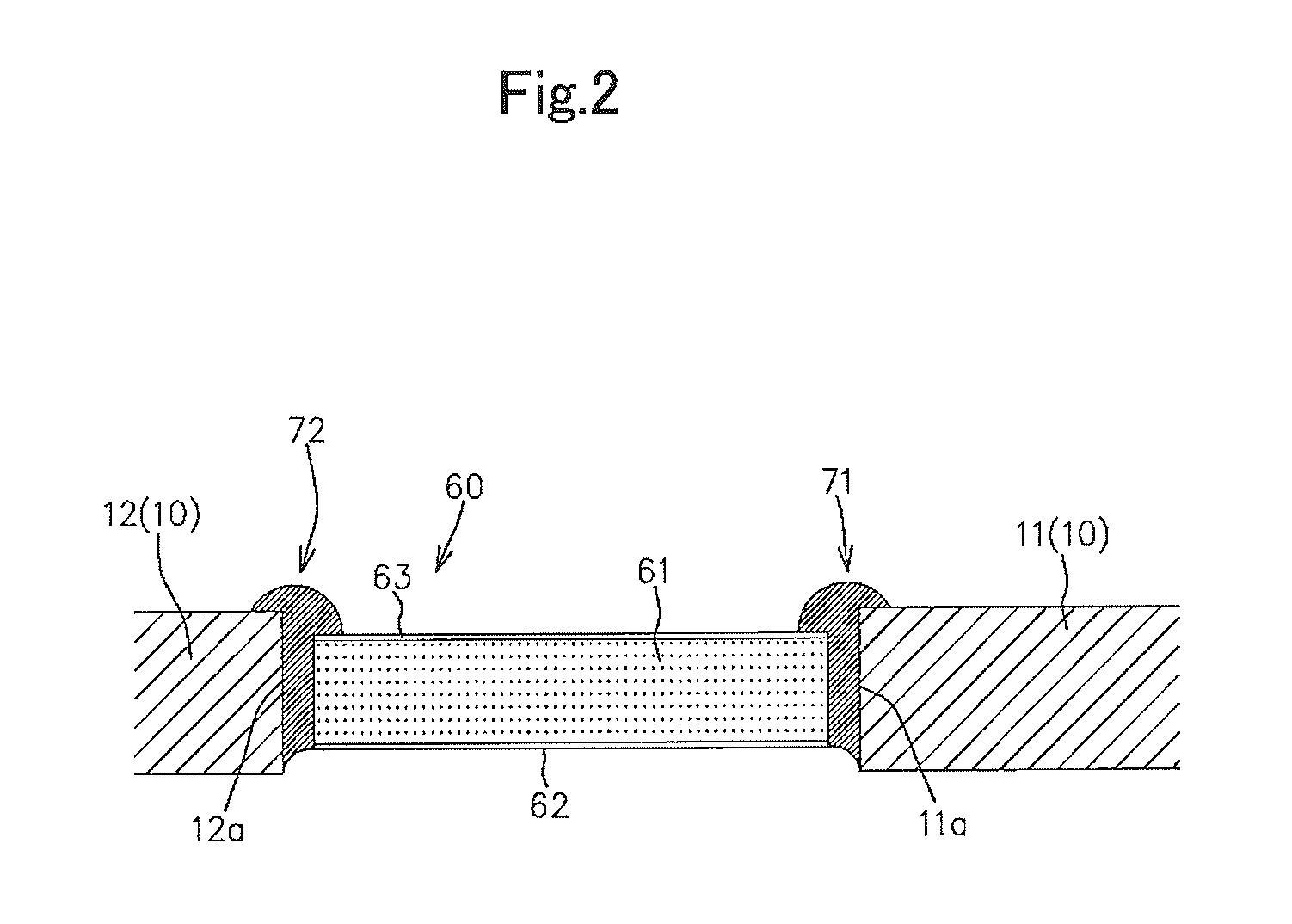
[0059]FIG. 2 is a cross sectional view taken along line II-II in FIG. 1A.

[0060]As shown in FIGS. 1A and 1B, the magnetic head suspension 1A includes a load bending part 20 that generates a load for pressing a magnetic head slider 50 toward a disk surface, a load beam part 30 that transmits the load to the magnetic head slider 50, a supporting part 10 that supports the load beam part 30 via the load bending part 20 and is swung about a swing center in a seek direction parallel to the disk surfa...

second embodiment

[0141]Hereinafter, another embodiment of the magnetic head suspension according to the present invention will be described, with reference to the attached drawings.

[0142]FIGS. 7A and 7B are a top view and a bottom view of a magnetic head suspension 2A according to the present embodiment. FIG. 7B indicates welding points with using small circles.

[0143]FIGS. 8A and 8B are cross sectional views taken along line VIII(a)-VIII(a) and line VIII(b)-VIII(b) in FIG. 7A, respectively.

[0144]In the figures, the members same as those in the first embodiment are denoted by the same reference numerals to omit the detailed description thereof.

[0145]Furthermore, FIG. 9A is a top view of the magnetic head suspension 2A in a state where the paired piezoelectric elements 60 and the insulative adhesive agents 70 are removed therefrom, and FIG. 9B is a top view of a flexure part 40B of the magnetic head suspension 2A. FIG. 9A shows the paired piezoelectric elements 60 with a dashed line.

[0146]As shown in ...

third embodiment

[0184]Hereinafter, still another embodiment of the magnetic head suspension according to the present invention will be described, with reference to the attached drawings.

[0185]FIG. 13 is a top view of a magnetic head suspension 3A according to the present embodiment.

[0186]FIGS. 14A and 14B are cross sectional views taken along line XIV(a)-VIV(a) and line XIV(b)-XIV(b) in FIG. 13, respectively.

[0187]In the figures, the members same as those in the first and second embodiments are denoted by the same reference numerals to omit the detailed description thereof.

[0188]As shown in FIGS. 13, 14A and 14B, the magnetic head suspension 3A according to the present embodiment is different from the magnetic head suspension 2A mainly in that the supporting part 10 is replaced with a supporting part 10C.

[0189]FIG. 15 is a top view of the supporting part 10C.

[0190]As shown in FIGS. 13 and 15, the supporting part 10C includes the components of the supporting parts 10, 10B, and also includes a centra...


PUM

PropertyMeasurementUnit
thicknessaaaaaaaaaa
thickaaaaaaaaaa
thicknessaaaaaaaaaa

Abstract

In a magnetic head suspension, a piezoelectric element is disposed within a supporting part's open section so that at least a part of its distal-side end surface faces a distal-side wall surface of the supporting part's distal end section forming a distal-side gap between the distal-side end surface and the distal-side wall surface and at least a part of its proximal-side end surface faces a proximal-side wall surface of the supporting part's proximal end section forming a proximal-side gap between the proximal-side end surface and the proximal-side wall surface in a state where the piezoelectric element's upper and lower electrode layers do not face the supporting part and any rigid members that are fixed to the supporting part. The piezoelectric element is fixed to the supporting part by a distal-side insulative adhesive agent and a proximal-side insulative adhesive agent.

Description

BACKGROUND OF THE INVENTION[0001]1. Field of the Invention[0002]The present invention relates to a magnetic head suspension for supporting a magnetic head slider that reads and / or writes data from and to a recording medium such as a hard disk drive.[0003]2. Related Art[0004]Increase in capacity of a magnetic disk device requires improvement in accuracy for positioning a magnetic head slider on a target track. In this regard, there has been proposed a magnetic head suspension that includes paired piezoelectric elements functioning as a sub actuator and enables micro motion of the magnetic head slider in a seek direction by the paired piezoelectric elements in addition to coarse motion of the magnetic head slider in the seek direction by a main actuator such as a voice coil motor (for example, see Japanese Unexamined Patent Application Publication Nos. 2002-251854, 2009-080915 and 2002-050140, which are hereinafter referred to as prior art documents 1-3, respectively).[0005]More speci...

Claims


Application Information

Patent Timeline
Patent Type & Authority Patents(United States)
IPC IPC(8): G11B5/56
CPCG11B5/4833G11B5/4873
Inventor FUJIMOTO, YASUOTAKASUGI, SATORUMASHIMO, KENJI
Owner SANCALL CORP
Why Eureka
Try Eureka