Spring pad for a sheet ironing machine

a technology of spring pad and sheet ironing machine, which is applied in the field of spring pad, can solve the problems of thinness of the felt cover rolled on the top plate, and achieve the effects of improving drying effect, improving finishing quality and reducing the cost of the sheet ironing machin

Active Publication Date: 2007-07-03
SANAI IND
View PDF10 Cites 0 Cited by
  • Summary
  • Abstract
  • Description
  • Claims
  • Application Information

AI Technical Summary

Benefits of technology

[0007]The present invention seeks to provide a solution to the inconvenience of the conventional arrangement. As such, there is provided a spring pad for a sheet ironing machine of which adjacent top plates have no space between them, and which preferably overlap each other when a backing strip of the spring pad is rolled on the periphery of the roller. This results in no traces of wrinkles or marks on the item to be ironed. Additionally, the felt cover rolled on the top plates is thin. Furthermore, the spring pad enables a reduction in cost of the sheet ironing machine, thanks to the thin felt cover to be used as well as improved finishing quality and drying effect due to the increased ventilation.
[0011]Said top plates 4 are arranged so that adjacent top plates 4 overlap each other, when the backing strip 2 of the spring pad is rolled on the periphery of roller R. Preferably, the direction of overlap is in the opposite direction to the direction of rotation of roller R. In other words, when the roller R is rotating in its normal operating condition, a leading edge of each top plate is received below a trailing edge of the next adjacent top plate. This prevents or reduces the possibility that one or more top plates are deformed and also that the top cover is removed from the claws as the roller R is rotating.
[0016]The present invention provides for adjacent top plates 4 with no spaces between them, and which overlap each other when the backing strip 2 is rolled on the periphery of the roller, thus making no traces of wrinkles on the item to be ironed, even though the felt cover F, which is rolled on the top plates, is thin. Furthermore, the spring pad enables a reduction in the of the sheet ironing machine P, thanks to the thin felt cover to be used, as well as improving the finishing quality and drying effect due to the increased ventilation.
[0018]Due to the said adjacent top plates 4 being overlapped with each other, and this providing an almost or substantially flat or smooth surface when the backing strip 2 is rolled on the periphery of roller R, the surface of said felt cover F can be kept scar- or mark-free, even though said felt cover, which is rolled on all surfaces of the said top plate 4, is thin.
[0019]Said positioning means 5 are formed backwardly at the ventilation hole 4B of said top plate 4 to extend towards the coil spring. The positioning means are typically a pair of guides or arms provided in close spaced relationship, thus enabling easy attachment of said top plate 4 onto the coil spring 3. The positioning means 5 also improve ventilation of the felt cover F, rolled on the top or upper surfaces of said top plates 4.
[0020]Each ventilation hole 4B of said top plate 4 is located opposite to or confronted with a respective ventilation hole 2B of backing strip 2. This improves the ventilation of the felt cover F, by providing an air flow path through the ventilation holes 4B of the top plates 4 and ventilation holes 2B of backing strip 2. Thus in the finishing stage of the ironing process, the residual water in the ironed item becomes steam, which is be exhausted to the roller side through the ventilation holes 2B of backing strip 2.

Problems solved by technology

Additionally, the felt cover rolled on the top plates is thin.

Method used


Image

  • Spring pad for a sheet ironing machine
  • Spring pad for a sheet ironing machine
  • Spring pad for a sheet ironing machine

Examples


Embodiment Construction

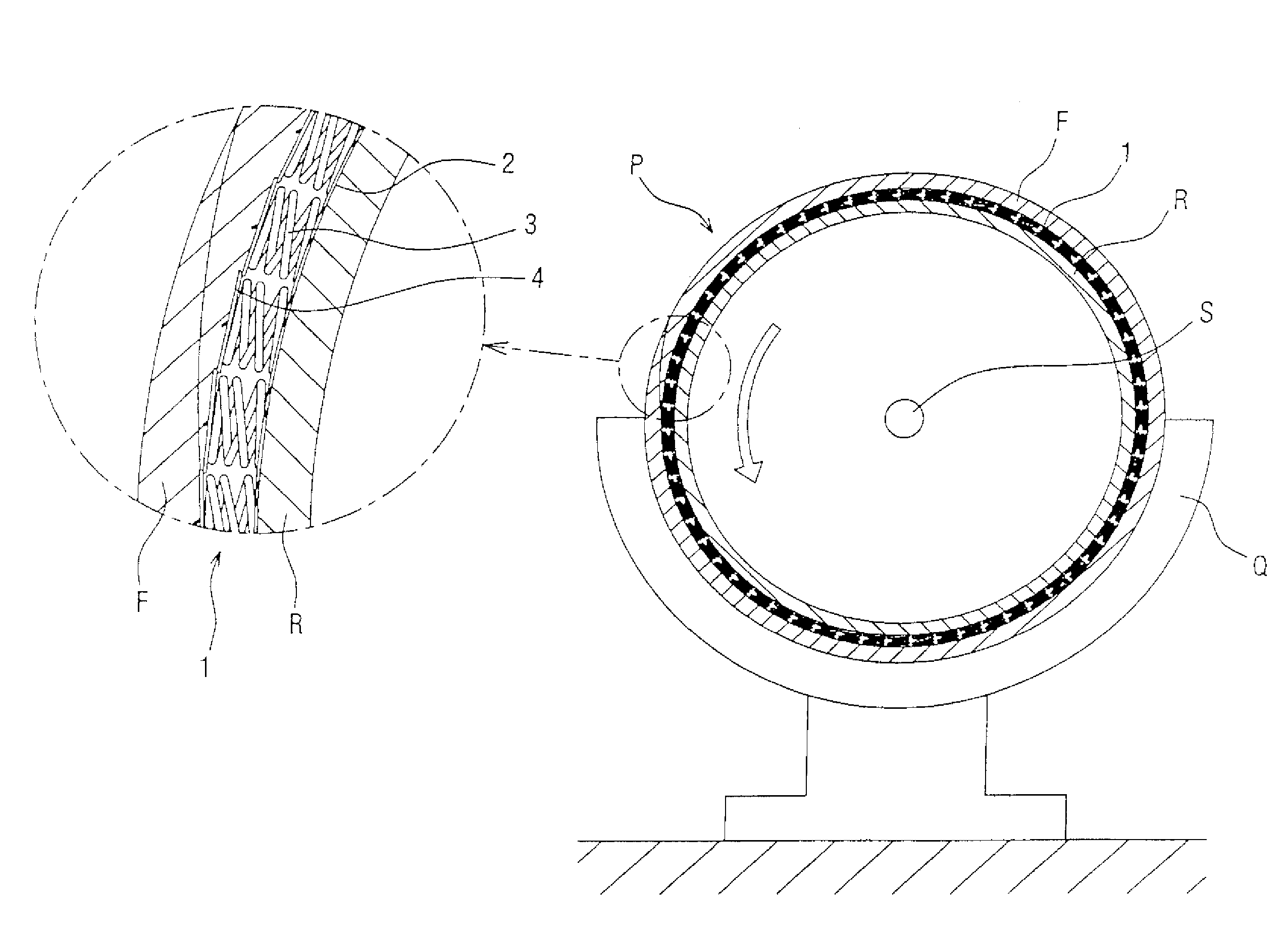
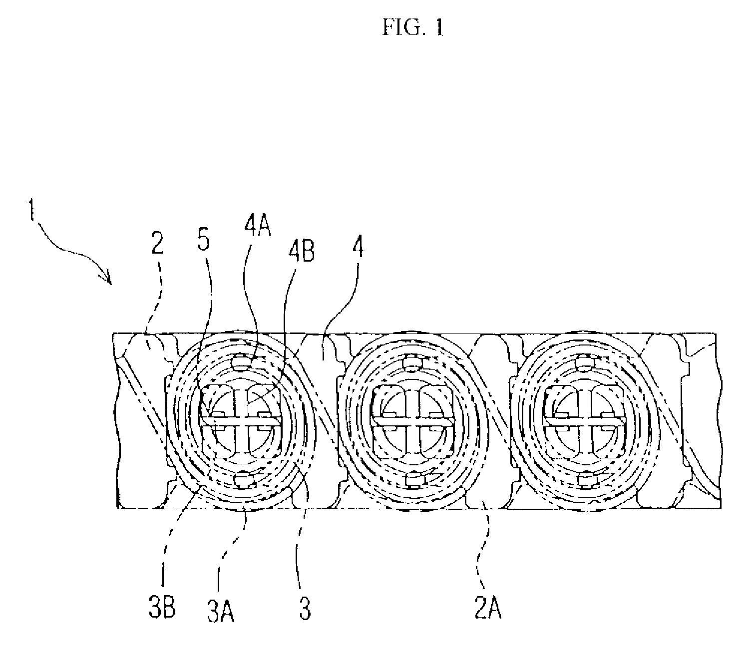
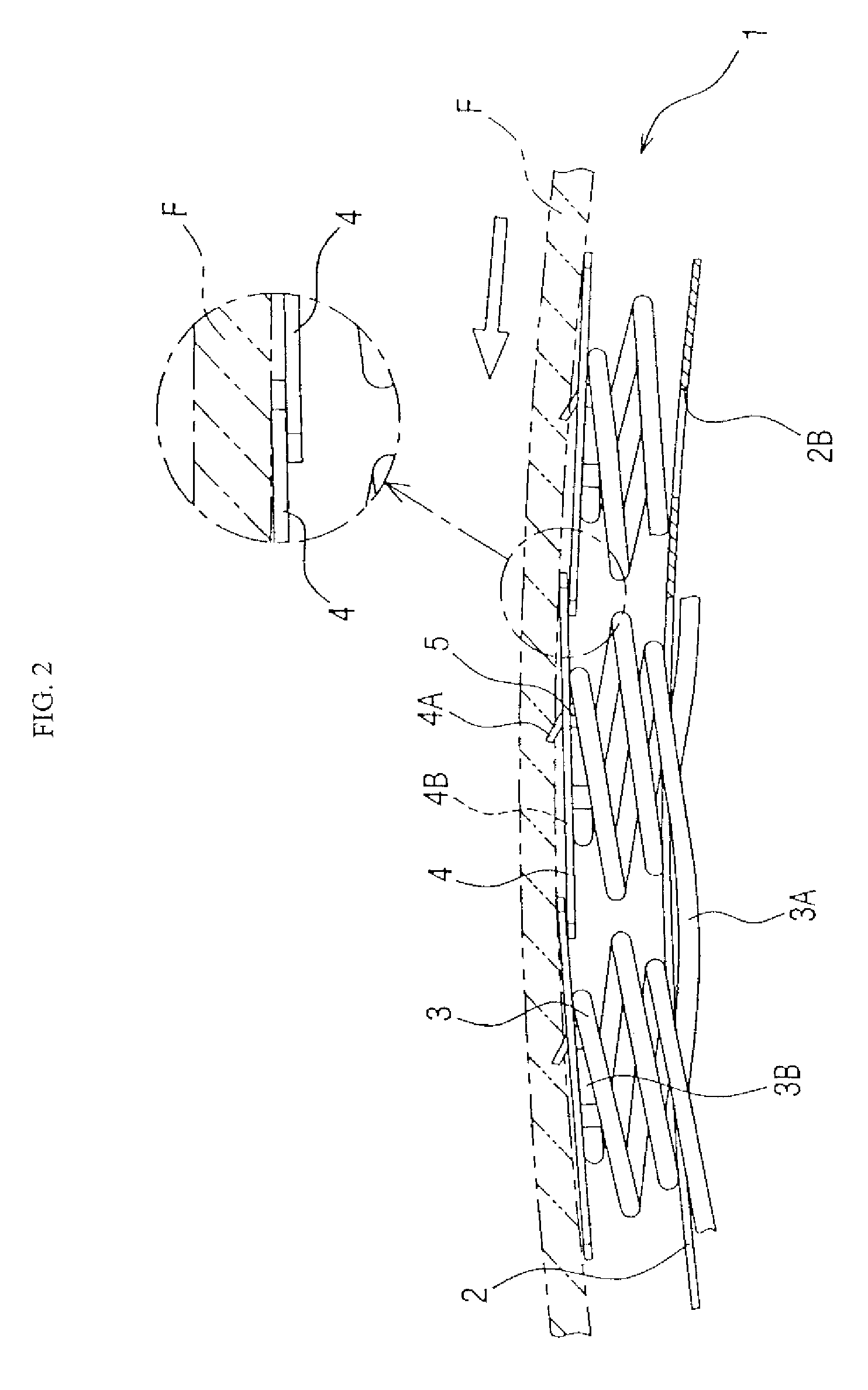
[0028]Referring to the drawings, spring pad 1, best seen in FIG. 6, has a long belt shape and is spirally rolled from one end to another end of the roller R, along the peripheral surface thereof. Felt cover F is then rolled on the periphery of the spring pad 1, and the spring pad 1 thus elastically supports the felt cover F.

[0029]The spring pad 1 is rolled on the roller R in such a manner that a first end of the spring pad 1 is fixed at the one side or end of the roller R, and then the spring pad 1 is rolled in a tight spiral along the peripheral surface of the roller R. The spring pad 1 is under tension, and its second end opposite the first end is connected to the other side or end of the roller R via a tension spring (not shown) which has hooks at both ends.

[0030]The sheet ironing machine shown in FIG. 6 comprises the roller R which is cylindrically formed to rotate around rotational axis S and which is arranged to contact a half-cylindrical bed Q or so called “chest”. Bed Q is s...


PUM


Abstract

An elongate spring pad for a sheet ironing machine includes an elongate backing strip, coil springs, and top plates. The backing strip encircles a roller of a sheet ironing machine. The coil springs are longitudinally spaced along the backing strip. Each coil spring has a connecting portion at a first end engaging the backing strip and a fixing portion at a second, opposite end that transverses the coil spring. Each of the top plates is provided on the second end of the respective coil spring. Positioning means on each top plate engage the respective coil spring. A claw projects outwardly from the top plate for releasably engaging a felt cover. Each top plate contacts an adjacent top plate so that there are no spaces therebetween.

Description

BACKGROUND OF THE INVENTION[0001]This invention relates to a spring pad for elastically supporting a felt cover. The felt cover is rolled on the periphery of a rotatable drum of a sheet ironing machine which is used to press and finish a flat sheet of material, such as a bed sheet, table cloth and so on.[0002]The item to be ironed, using the sheet ironing machine, is finished by putting the item between a roller or drum and a bed which is heated by steam or a thermal medium of oil. The finishing procedure results in the drying, pressing and ironing, whilst the residual water contained in the washed item becomes vapour due to the heated bed. The vapour is discharged from the side of the roller.[0003]On the periphery of the rotatable drum is rolled a spring pad, on the outer periphery of which is positioned a felt cover.[0004]Conventionally, there is known a spring pad as disclosed in patent application EP0736627A1 by the same applicant as the present application. The said spring pad ...

Claims


Application Information

Patent Timeline
Patent Type & Authority Patents(United States)
IPC IPC(8): D06F83/00D06F69/02
CPCD06F83/00
Inventor MOTODA, SHUHO
Owner SANAI IND
Why Eureka
Try Eureka