
Hyperbaric chamber control and/or monitoring system and methods for using the same

a monitoring system and hyperbaric chamber technology, applied in the field of hyperbaric chambers, can solve the problems of inefficiency of prior art hyperbaric chambers, compromising patient care, and calibrating pressure gauges

Inactive Publication Date: 2012-08-28
LIFE SUPPORT TECH
View PDF149 Cites 5 Cited by
  • Summary
  • Abstract
  • Description
  • Claims
  • Application Information

AI Technical Summary

Benefits of technology

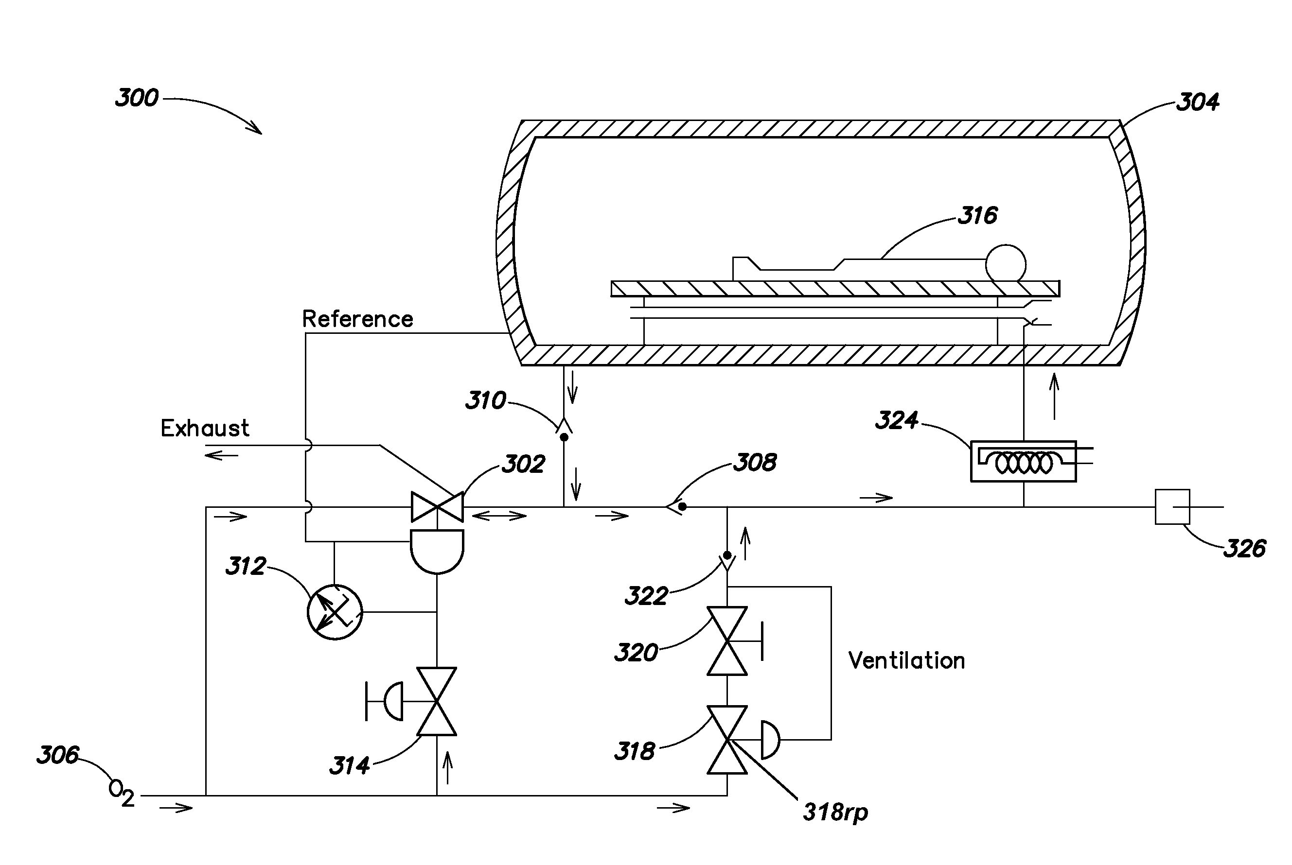
[0018]In accordance with some embodiments of the invention, there is provided a flow controller that may be coupled between a pressurized gas supply and a valve wherein the flow controller includes a reference port coupled to an outlet port of the valve and to a one-way inlet port of a hyperbaric chamber. In some embodiments, the flow controller is coupled to a primary ventilation gas, a focused ventilation gas, and/or a mask gas. In some embodiments, the valve includes a control coupled to, and operable by, an electric-to-pneumatic transducer coupled to a computer controller.
[0019]I

Problems solved by technology

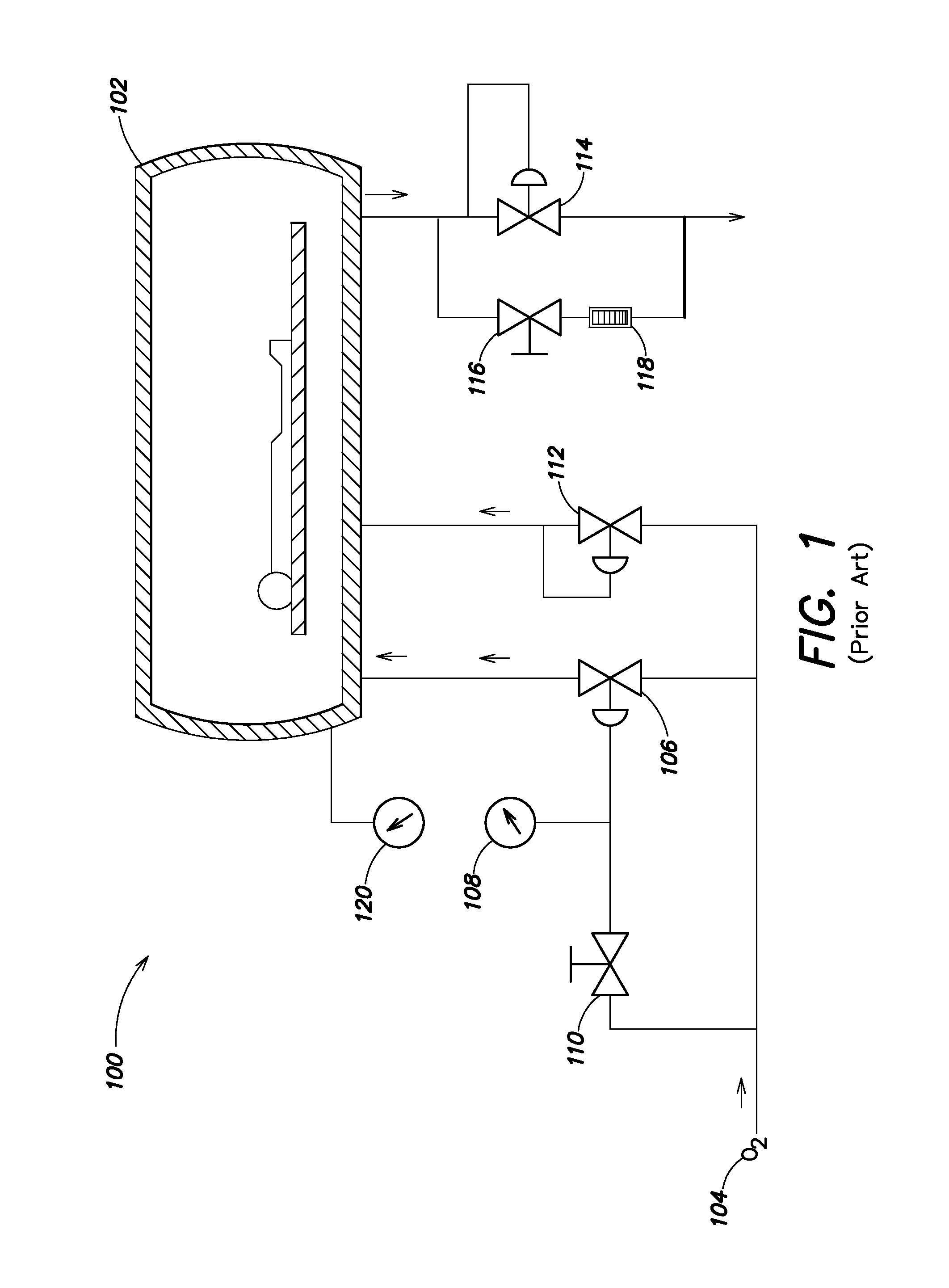
A significant problem with prior art hyperbaric chamber control systems is that they require equally zeroed and calibrated pressure gauges at atmospheric pressure to not read the same pressures for a given treatment depth.
This necessary miscalibration has often resulted in operator confusion due to the difference between the gauges which may result in operator error that may compromise patient care.
This further contributes to the inefficiency of prior art hyperbaric chambers 102.
In many areas of the world, medical grade compressed oxygen suitable for use in a hyperbaric chamber 102 is expensive and not readily available.
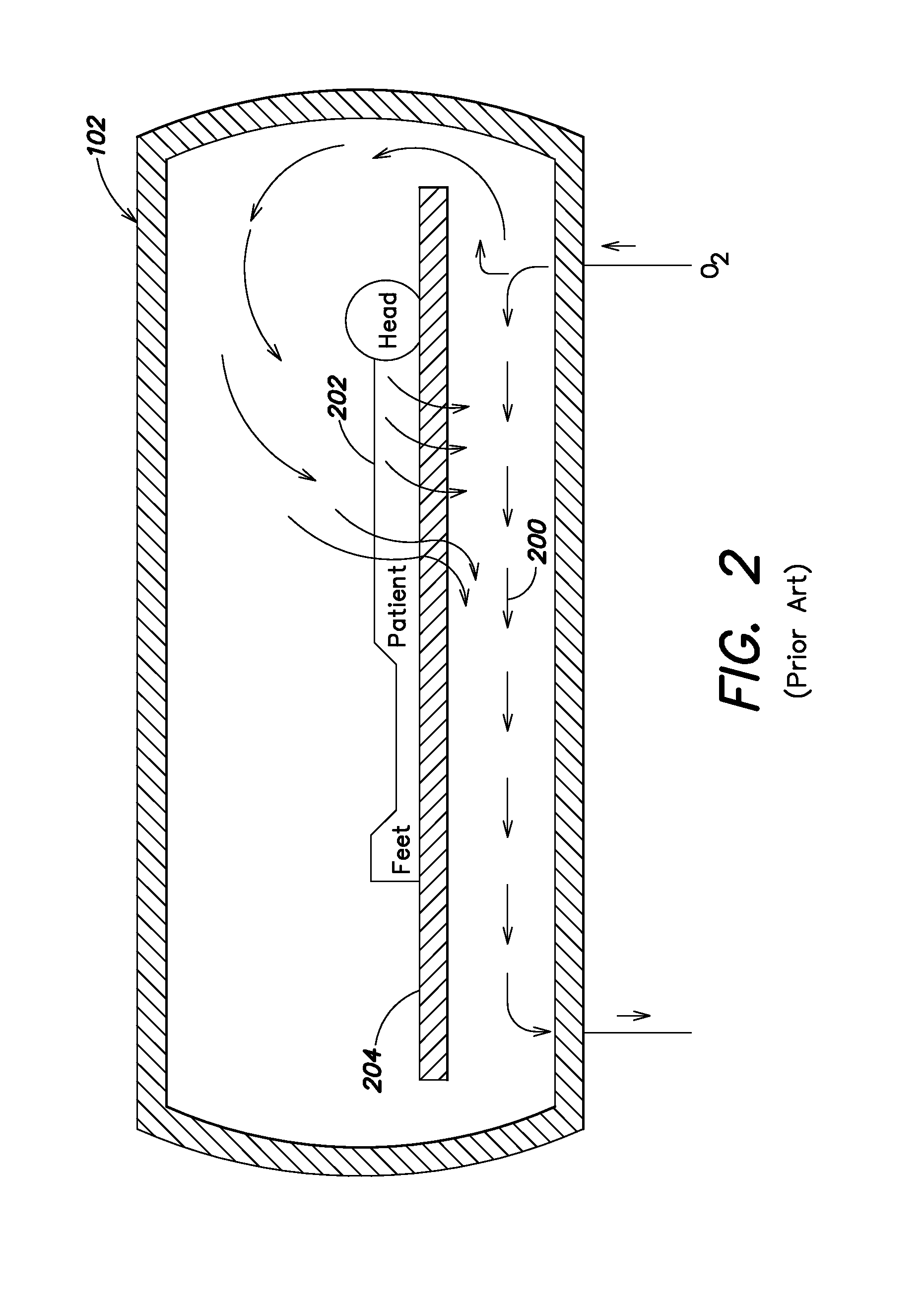
Thus, it is a substantial drawback of prior art chambers 102 that they must use high volumes of oxygen.
In addition, using such high volumes of oxygen results in significant noise levels within the chamber 102 which may be unpleasant for patients that may be subjected to the loud noise for prolonged periods during treatment.

Method used


Image

  • Hyperbaric chamber control and/or monitoring system and methods for using the same
  • Hyperbaric chamber control and/or monitoring system and methods for using the same
  • Hyperbaric chamber control and/or monitoring system and methods for using the same

Examples


Embodiment Construction

[0029]The present invention provides specific and significant improvements in pressure control, lower oxygen consumption, temperature and humidity environmental control, and safety as compared to control systems of prior art monoplace hyperbaric chambers presently available in the worldwide marketplace.

[0030]As illustrated in FIG. 3, in some embodiments of the present invention a hyperbaric chamber control system 300 uses, for example, a pneumatic volume booster 302 to both provide oxygen to pressurize the chamber 304 and to provide controlled exhaust of the chamber 304. The inlet port of the booster 302 is coupled to an oxygen supply 306 and the outlet port of the booster 302 is coupled to a check valve 308 leading to the chamber 304. The check valve 308 prevents oxygen from flowing back from the chamber 304.

[0031]The outlet port of the booster 302 is also coupled to a check valve 310 leading from an exhaust outlet of the chamber 304. Check valve 310 (e.g., a gravity swing check va...


PUM


Abstract

In a first aspect, a monoplace hyperbaric chamber providing Venturi induced gas circulation and ventilation is disclosed. The chamber includes a control and monitoring system that offers reduced oxygen consumption, duplex pressure gauges, referenced flow control, a patient activated stop function, an independent pressure time recorder, and / or a precise pressure control circuit that uses a 1:1 forced-balanced volume amplifier adapted to supply gas to and exhaust gas from the chamber through different penetrators and / or use flow-control check valves supplied with static reference or set pressures. A computer control and monitoring subsystem is also disclosed. Numerous other aspects are provided.

Description

[0001]This application claims priority from U.S. Provisional Patent Application No. 60 / 483,754, filed Jun. 30, 2003 and entitled “HYPERBARIC CHAMBER CONTROL AND / OR MONITORING SYSTEM AND METHODS FOR USING THE SAME” which is incorporated herein by reference in its entirety for all purposes.FIELD OF THE INVENTION[0002]The present invention relates generally to hyperbaric chambers, and more particularly to a hyperbaric chamber control and / or monitoring system and methods for using the same.BACKGROUND OF THE INVENTION[0003]Monoplace hyperbaric chambers are designed to provide oxygen therapy under a specific pressure profile for one patient at a time. Such chambers typically have basic pressure control and monitoring systems. A commercially available example of a conventional chamber is the Model 3200 Monoplace Hyperbaric Chamber manufactured by Sechrist Industries, Inc. of Anaheim, Calif. These chambers typically include a series of manual gas valves that allow an operator to control inp...

Claims


Application Information

Patent Timeline
IPC IPC(8): A61G10/00A61M15/00B24D13/00G01L7/00H01G7/00A61G10/02B63C11/32
CPCA61G10/026B63C11/325
Inventor BUTLER, GLENN
Owner LIFE SUPPORT TECH
Learn More