Anti-sink rim

a technology of anti-slip rims and rims, which is applied in the direction of auxillary traction increasing equipment, wheel attachments, multi-wheel assemblies, etc., can solve the problems of inability to prevent from one another, limited distance effect, and risk of injury

Active Publication Date: 2012-08-28
BIESSE PHILIPPE
View PDF27 Cites 4 Cited by
  • Summary
  • Abstract
  • Description
  • Claims
  • Application Information

AI Technical Summary

Benefits of technology

[0013]This light rim consists of a support flange (1.1) which is maintained against the wheel disc by some locking bolts, and which is extended by a rim profile (1.2) which has a conical shape that lends its mechanical stiffness and allows, when not in use, stacking of the rims one inside the other for a minimum storage volume in the trunk of the vehicle.
[0014]A tire, the surface of which constitutes the desired additional tread, fills in the space between the anti-sink rim profile and the outside wall of the vehicle tire which constitute its supports. The system outside diameter is smaller than the outside diameter of the existing tire that remains the main carrying element of the vehicle. This difference in outside diameter also allows for an easy mounting of the anti-sink rim on the wheel as son as the a risk of getting stuck appears with the start of sinking of the wheel into the soil, and reduces the risks of contact between the anti-sink rims mounted on the front steering wheels and the body of the vehicle. As shown on the drawings and described more in details, there are different embodiments with variations for tires, rim profiles, centering surfaces and fixation types. According to its material, the tire can be fit on the anti-sink rim before or after mounting on the wheel.

Problems solved by technology

The main drawback of these remedial solutions is that they do not prevent from another problem further down on the track.
Their effects are very limited in distance.
Further more they require the availability of another vehicle, men or animals for pushing, and there are risks of injuries when pushing or pulling a vehicle, or the tow vehicle can also get stuck.
In addition, special tires are optimized for a specific type of track and may not be best suited for the other sections of the road and it is not conceivable to change tires according to each new type of road encountered.

Method used


Image

  • Anti-sink rim
  • Anti-sink rim
  • Anti-sink rim

Examples


first embodiment

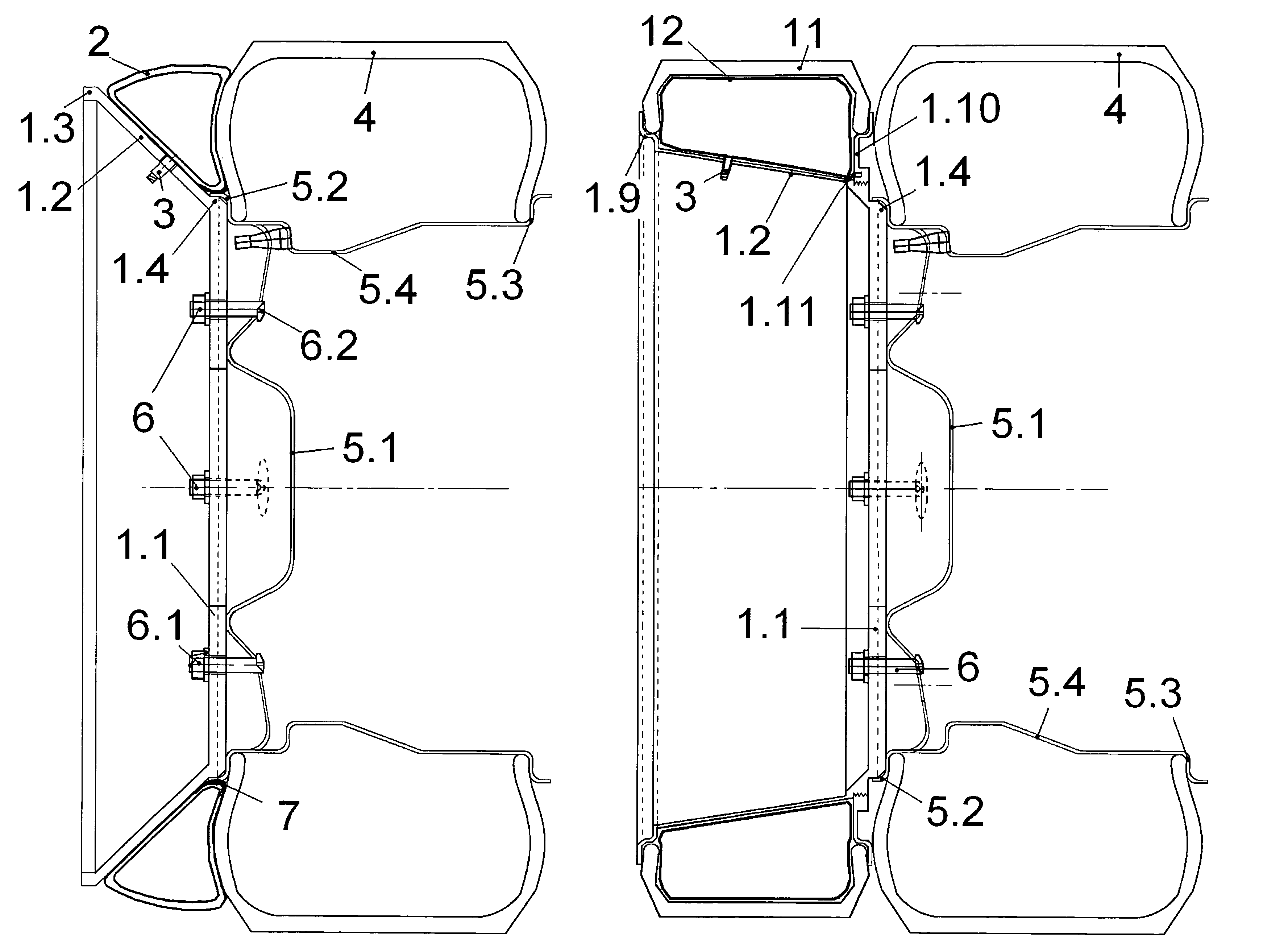
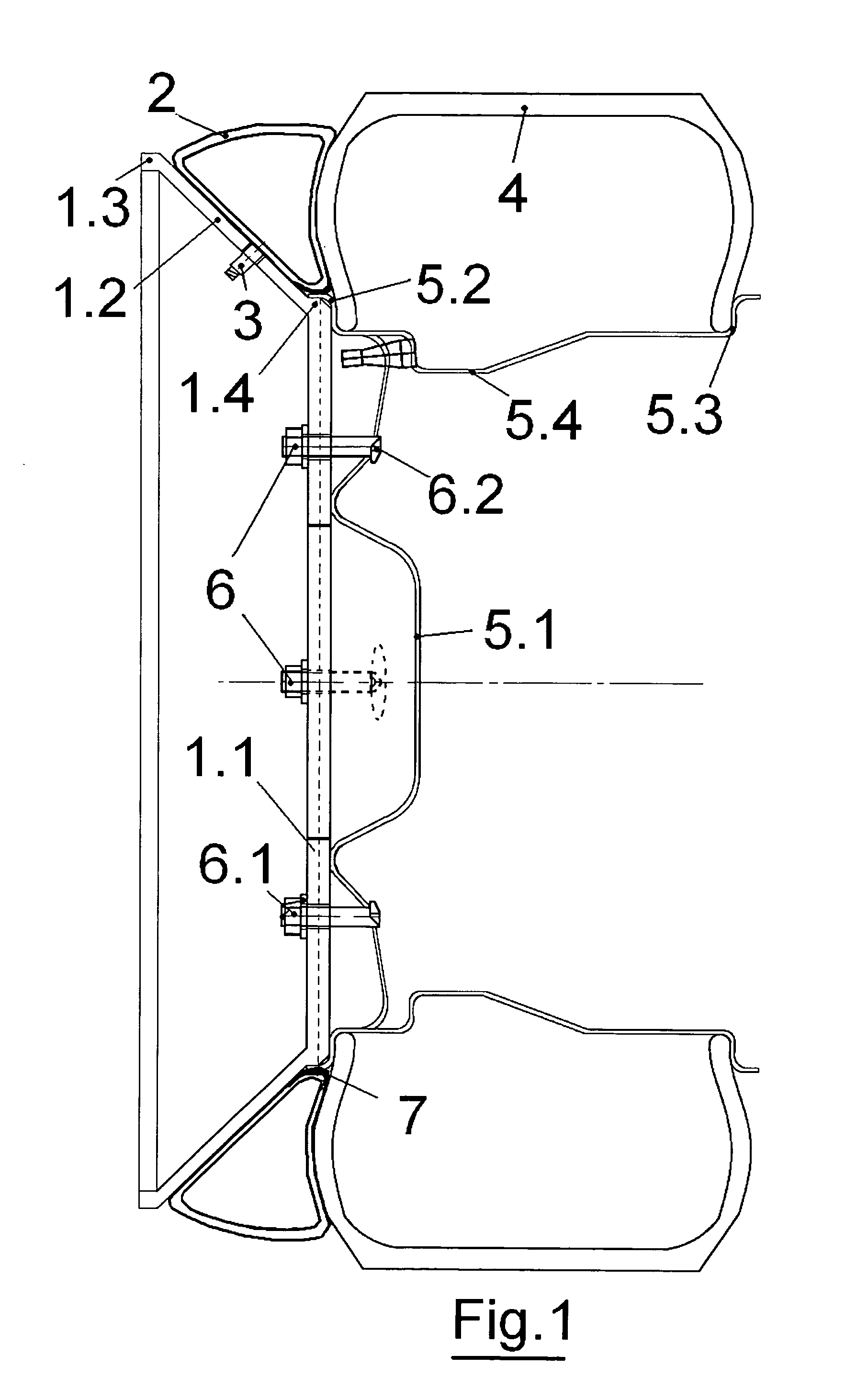
[0062]One first embodiment is illustrated in FIG. 1. The anti-sink rim structure (all items 1) is placed on the wheel. The distal annular surface (1.4) of its flange (1.1) is applied against the wheel rim outer surface at the level of the wheel rim edge (5.2) and the flange outer cylindrical surface (1.4) is centered inside the corner of the wheel rim edge (5.2). The locking bolts (6) which are composed of a nut, a washer and a threaded stud (6.1) extended by a hook (6.2) are inserted and coupled in respective openings in the flange (1.1) and rim (5.1) for insuring contact pressure between the flange (1.1) and the wheel disc. The conical rim profile (1.2) is supported on the flange outer diameter on one side and is reinforced by a ring (1.3) on the other side. The material of the system tire is a thick inflated tube (2) that is supported between the rim profile (1.2) and the existing tire (4) wall located on the outside of the vehicle. The tube is protected from possible damaging co...

second embodiment

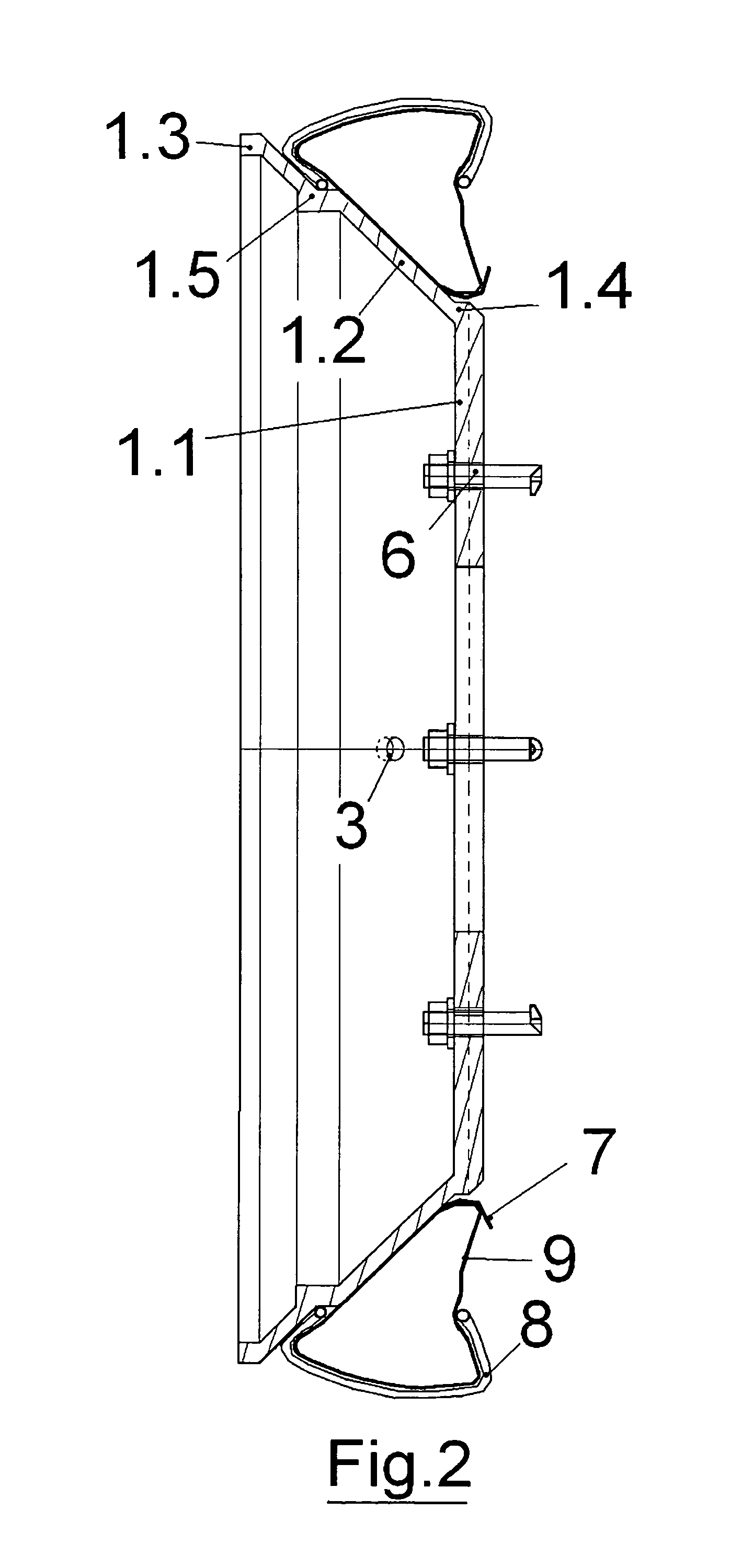
[0073]In a second embodiment corresponding to FIG. 2, the material of the system tire is a regular tube (9) put inside a light tire (8). This tire similar to a mopped tire will be centered on a support (1.5) provided on the rim profile (1.2) on the outer side, and will be free on the vehicle side. The tube (9) inside pressure will guarantee enough friction at the bead wires and walls of the light tire (8) to transmit the required torque without twisting.

[0074]Any protuberance on the inside surface of the cone resulting from the shape of the support (1.5) will be smoothed so that it does not prevent stacking of the rims for minimized storage volume. In this drawing the centering of the anti-sink rim is made between the outside cylindrical part of the flange (1.4) and the rim edge (5.2), the rim conical profile (1.2) is reinforced (1.3), the inner tube (9) is protected from contact with the edge of the wheel rim by the protective tape (7).

third embodiment

[0075]With the third embodiment shown in FIG. 3, the anti-sink rim is widened. The shape of its profile (1.2) is here broken down into various sections (1.2a and 1.2b) with flare angles increasing in the outer direction in order to preserve a good ratio between width, stiffness and the possibility of stacking the rims one inside the other for optimized storage. The tread will be composed of several rings or reinforced tubes (10a and 10b). These kinds of rings ensure enough bearing capacity on many types of soil, including sand dunes.


PUM


Abstract

Device used to free a vehicle that is stuck in terrain or to reduce such risk through the use of an additional tread disposed parallel to each wheel of the vehicle. The additional tread can be an air chamber (2 or 10a and 10b) covered or not with a tire (11) or a band comprising different coupling profiles (13, 14 or 15). The tread is mounted onto an anti-sink rim comprising a conical profile (1.2) and a flange (1.1) centered in and applied against the outer side of the wheel disc by special bolts (6) inserted in respective openings in the flange and rim. The diameter of the system is smaller than that of the wheel to facilitate mounting and to avoid interference with the vehicle body. The conical shape of the rim profile (1.2) lends stiffness and enables the rims to be stacked for reduced storage volume in trunk.

Description

CROSS-REFERENCE TO RELATED APPLICATIONS[0001]Not ApplicableSTATEMENT REGARDING FEDERALLY SPONSORED RESEARCH OR DEVELOPMENT[0002]Not ApplicableTHE NAMES OF THE PARTIES TO A JOINT RESEARCH AGREEMENT[0003]Not ApplicableINCORPORATION BY REFERENCE OF MATERIAL SUBMITTED ON A COMPACT DISC[0004]Not ApplicableBACKGROUND OF THE INVENTION[0005]1. Technical Field[0006]The invention relates to a device that is used to free a road or all tracks vehicle that has become stuck in terrain or to reduce the risk of the same. The terrain is made of sand, mud or snow or other soft material that would lead to the sinking of the wheel in the upper layer of soil together with a reduced traction. According to the terrain characteristics and slope of the track, it also helps reduce the difficulties associated with lack of traction of the vehicle on the track material.[0007]2. Background Art[0008]In case a vehicle is stuck, it is known in the vehicle art that one can use special light boards (L×W=2×0.5 m) to f...

Claims


Application Information

Patent Timeline
Patent Type & Authority Patents(United States)
IPC IPC(8): B60B11/10B60B15/26
CPCB60B15/263B60B19/04B60B11/10
Inventor BIESSE, PHILIPPE
Owner BIESSE PHILIPPE
Why Eureka
Try Eureka