
Heating device for a motor vehicle operating fluid tank with a PTC plastic element

a technology of operating fluid tank and heating device, which is applied in the direction of heating element materials, heating element shapes, exhaust treatment, etc., can solve the problems of large danger to the safety of high temperature use and the desire for self-limiting of the heating power of the ptc-element, and achieve the effect of high degree of design freedom

Inactive Publication Date: 2017-09-07
ROECHLING AUTOMOTIVE SE & CO KG
View PDF3 Cites 8 Cited by
  • Summary
  • Abstract
  • Description
  • Claims
  • Application Information

AI Technical Summary

Benefits of technology

The invention is a heating device for a motor vehicle operating fluid tank that can be easily installed without taking up too much space. The device is made by bonding a thin metal foil with a plastic film, which makes it easier to handle during manufacture. The device can also be protected from chemical attack by using a plastic film as a shell. Additionally, the invention allows for a heating path to be created on a foil or plate and then covered with a plastic film for protection. The plastic film can be glued or laminated directly onto the substrate. Overall, the invention provides a compact, efficient, and customizable heating solution for operating fluid tanks.

Problems solved by technology

This leads to a desirable self-limiting of heating power of a PTC-element.
The chemical stability of the aqueous urea solution of special interest here decreases at temperatures of more than 80° C., so that its safety of use at high temperatures is greatly endangered.

Method used


Image

  • Heating device for a motor vehicle operating fluid tank with a PTC plastic element
  • Heating device for a motor vehicle operating fluid tank with a PTC plastic element
  • Heating device for a motor vehicle operating fluid tank with a PTC plastic element

Examples


first embodiment

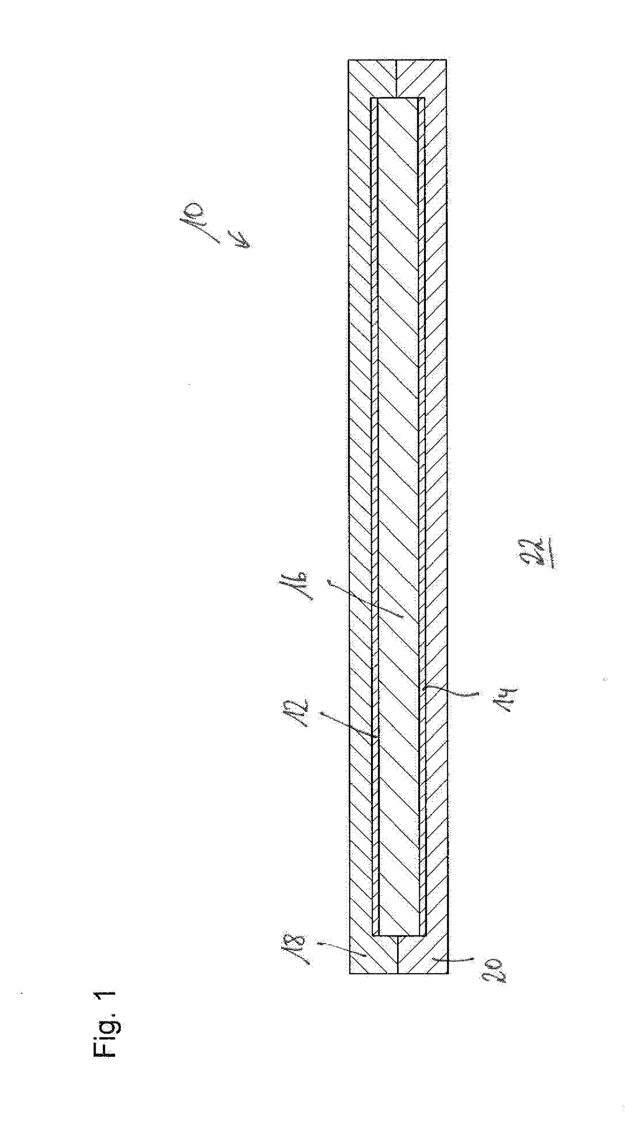
[0040]FIG. 1 shows a heating device according to the invention identified overall with reference numeral 10. The heating device comprises a first metal foil 12 and a second metal foil 14 as electrical conductors and a plastic element 16 made of PTC plastic arranged between the two metal foils 12 and 14. The arrangement of the metal foils 12 and 14 as well as the PTC plastic element 16 is located between the two plastic films 18 and 20, which hermetically shield the electrically conducting components 12, 14, and 16 from the outside environment, so that neither the metal foils 12 and 14 nor the PTC plastic element 16 can be touched or wetted by a medium in the outer environment 22. This is advantageous in particular if the heating device 10 is provided for emitting heat to a substance that is chemically aggressive toward at least one of the materials of the heating device, as is the case, for example, with aqueous urea solution.

[0041]The metal foils 12 and 14 are preferably aluminum f...

second embodiment

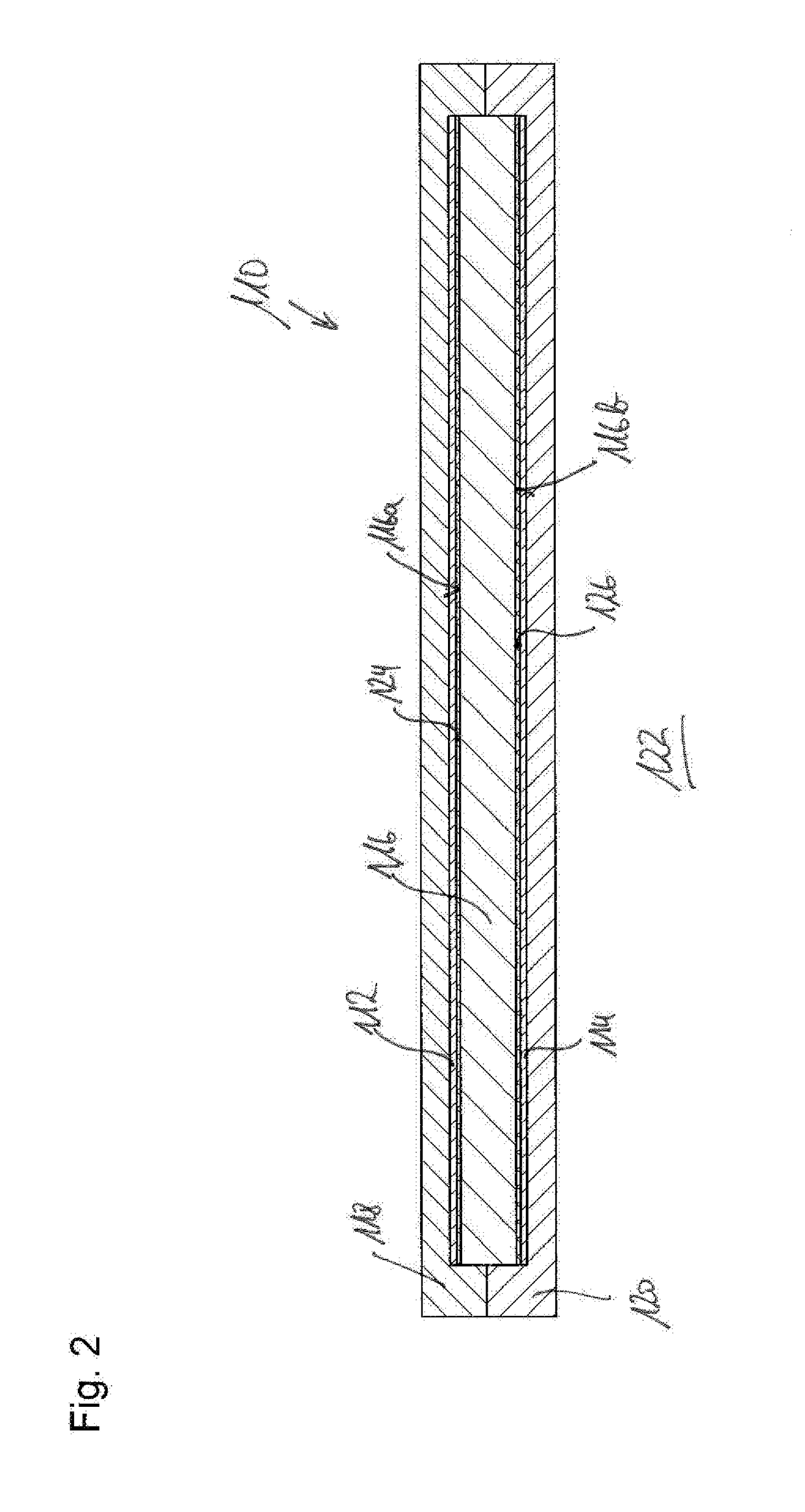
[0048]FIG. 2 shows a heating device according to the invention in the same perspective as in FIG. 1.

[0049]Components and component sections that are identical and functionally equivalent to those in the first embodiment are provided with the same reference numeral, but increased by the number 100, in the second embodiment. The second embodiment of FIG. 2 will be described below only to the extent that it differs from the first embodiment in FIG. 1, to whose description reference is expressly made to describe the second embodiment.

[0050]The second embodiment differs from the first only in that a metal layer is applied on the surfaces 116a and 116b that face the metal foils 112 and 114, for example, by precipitation from the gas phase, as is possible by means of sputtering, in order to improve the electrical contact between the metal foils 112 and 114, on the one hand, and the PTC plastic element 116, on the other hand. The metal layers 124 and 126 are only a few nanometers thick, as ...

fourth embodiment

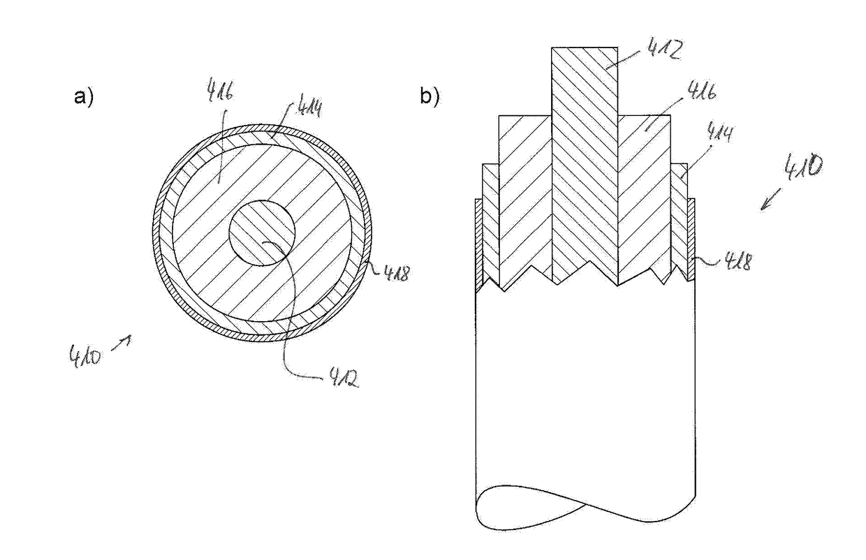
[0057]FIG. 4 shows a heating device 410 according to the invention.

[0058]Components and component sections that are identical and functionally equivalent to those in the first, second, or third embodiment are provided with the same reference numerals increased by the numbers 300, 200, or 100 in the fourth embodiment. The fourth embodiment of FIG. 4 will be described only to the extent that it differs from the first embodiment in FIG. 1 or the second embodiment in FIG. 2 or the third embodiment in FIG. 3, to whose description reference is expressly made to describe the fourth embodiment.

[0059]The heating device 310 of the fourth embodiment shows two electrical conductors 312 and 314, preferably again made from metal foil, which are locally bridged at various points by PTC plastic elements 316′, 316″ . . . 316IX. The PTC plastic elements are here either molded around the electrical conductors 312 and 314 or formed from two half-shells, which locally accommodate sections of the electri...


PUM


Abstract

A heating device (10) for a motor vehicle operating fluid tank, in particular for storing aqueous urea solution, wherein the heating device (10) has two electrical conductors (12, 14), an element (16) made from PTC plastic, which is electrically arranged between the two electrical conductors (12, 14) and is in electrical contact with the two electrical conductors (12, 14), and a shell (18, 20), which protects the electrical conductors and the PTC plastic element (16) from the outside environment (22) at least in some sections, which is characterized in that at least one electrical conductor (12, 14) is made at least in some sections from a metal foil (12, 14), in particular aluminum foil, and that the shell (18, 20) is an insulating surface, in particular a plastic film (18, 20) that is preferably bonded to the metal foil.

Description

CROSS REFERENCE TO RELATED APPLICATION(S)[0001]This application claims priority to German Application No. 10 2016 203 497.9, filed Mar. 3, 2016. The entirety of the disclosure of the above-referenced application is incorporated herein by reference.BACKGROUND OF THE INVENTION[0002]Field of the Invention[0003]The present invention relates to a heating device for a motor vehicle operating fluid tank, in particular for storing aqueous urea solution, wherein the heating device has two electrical conductors, an element made of PTC plastic arranged between the two electrical conductors and in electrical contact with the two electrical conductors, and a shell that protects the electrical conductors and the PTC plastic element at least partially from the outer environment.[0004]The invention likewise relates to a motor vehicle operating fluid tank, in particular for storing aqueous urea solution, having a filling opening, a removal opening different from the filling opening, and a heating de...

Claims


Application Information

Patent Timeline
Patent Type & Authority Applications(United States)
IPC IPC(8): F01N3/28H05B3/00F01N3/20H05B1/02
CPCF01N3/2896F01N3/206H05B3/0014H05B1/0236H05B3/10H05B3/36H05B3/56F01N3/2066H05B3/44H05B3/78F01N2610/02F01N2610/10H05B2203/02Y02A50/20Y02T10/12
Inventor CHINI, FABRIZIOMARINI, LUCADE METRI, IVANBRUNORI, FRANCESCADALPEZ, STEFANO
Owner ROECHLING AUTOMOTIVE SE & CO KG
Learn More