Reflective composite material comprising an aluminum substrate and a silver reflective layer

a composite material and reflective layer technology, applied in the direction of superimposed coating process, optical elements, instruments, etc., can solve the problem of faster loss of reflective capacity than, and achieve the effect of preventing delamination of low-refractive layer, smallest possible thickness, and improving adhesion to silver layer

Inactive Publication Date: 2018-08-30
ALANOD GMBH
View PDF4 Cites 4 Cited by
  • Summary
  • Abstract
  • Description
  • Claims
  • Application Information

AI Technical Summary

Benefits of technology

[0028]To improve the adhesion onto the silver layer and / or to prevent a delamination of the low-refractive layer from the silver layer, an additional adhesion promoting layer can be provided which likewise is in particular oxidic and can consist preferably of CrOs. In principle, the second adhesion-promoting layer herein can have a thickness which resides in the same range as that of the first adhesion-promoting layer. However, typically it should have the smallest possible thickness so that while attaining a satisfactory adhesion, the layer itself will cause only a very minor absorption.
[0029]As an additional, fourth layer, another, in particular silicon oxide and / or nitride covering layer can be placed over the highly refractive, upper layer of the optical multi-layer system. This fourth layer displays a high transmission capacity and improves the mechanical and corrosion resistance. An outstanding adhesion is to be obtained when a dielectric layer located directly underneath the covering layer is a Nb2O5 and Ta2O5 layer applied in a PVD (physical vapor deposition) method, wherein this also promotes a good hardness and elasticity of the invented composite material. Alternatively, a titanium dioxide layer is recommended. The covering layer of the optical multi-layer system herein can have a minimum thickness of 3 nm, for example. In particular, from a thickness of 5 nm to 20 mn, the layer already possesses a sufficient effectiveness of its protective effect, wherein the time, material and energy expense take on very small values. An upper limit to the layer thickness under these considerations is at about 500 nm.

Problems solved by technology

However, the problem with Miro®-Silver material, especially in long-term applications and when used in a hot environment, such as in hot climates or together with a light source which features a powerful heat radiation, is that there can be a faster loss of reflective capacity than for the already long-known Miro®-material whose reflective metallic layer consists of aluminum.

Method used


Image

  • Reflective composite material comprising an aluminum substrate and a silver reflective layer
  • Reflective composite material comprising an aluminum substrate and a silver reflective layer
  • Reflective composite material comprising an aluminum substrate and a silver reflective layer

Examples


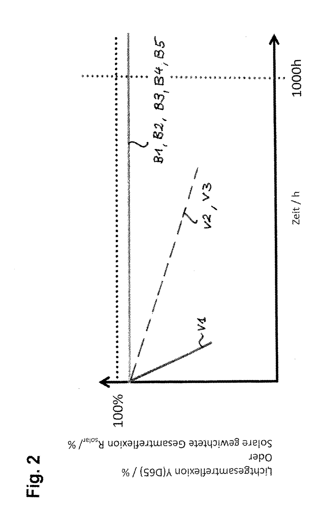
example 1 (according to invention , reference symbol b1 in fig.2)

Example 1 (According to Invention, Reference Symbol B1 in FIG. 2)

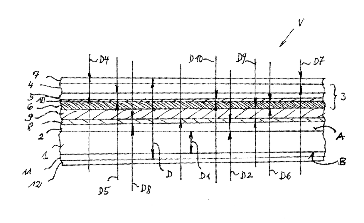
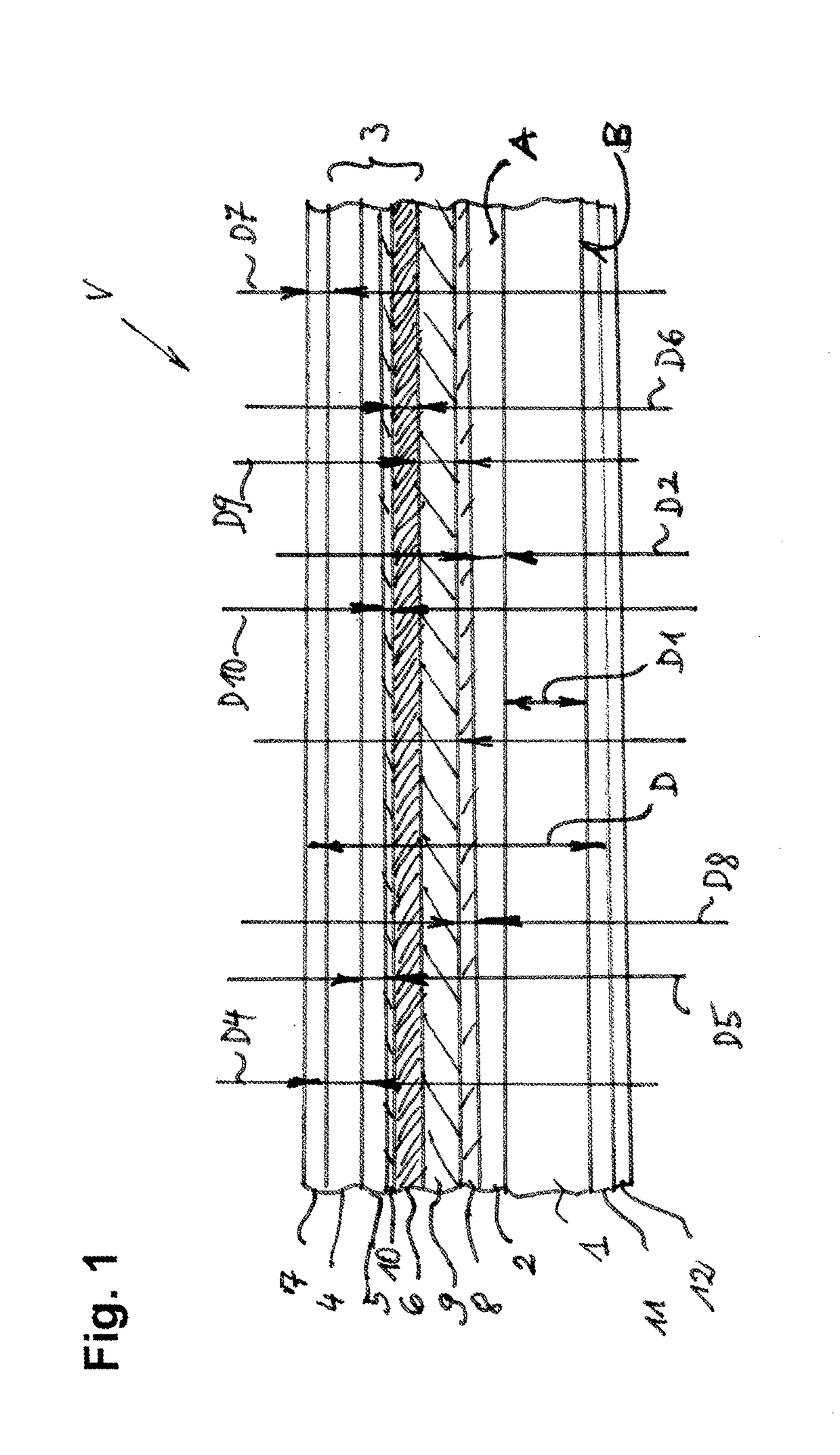
[0087]Layer system (from bottom to top):

[0088]Substrate 1: Aluminum

[0089]Intermediate layer 2: Anodized aluminum

[0090]Barrier layer 8: metallic chromium

[0091]Adhesion-promoting layer 9 between barrier layer 8 and reflective layer 6: TiO2

[0092]Reflective layer 6: Silver

[0093]Lower dielectric layer 5: Al2O3

[0094]Upper dielectric layer 4: Nb2O5

[0095]The lower dielectric Al2O3-layer 5 located over the intermediate layer 2 was applied by electron beam evaporation coating, whereas the upper dielectric Nb2O5-layer 4 was applied by magnetron sputter coating.

[0096]After 1000 hours the decrease ΔR in reflectivity amounted to less than 1%. The test was passed.

example 2 (according to the invention , reference symbol b2 in fig.2)

Example 2 (According to the Invention, Reference Symbol B2 in FIG. 2)

[0097]Layer system (from bottom to top):

[0098]Substrate 1: Aluminum

[0099]Intermediate layer 2: Anodized aluminum

[0100]Barrier layer 8: metallic chromium

[0101]Adhesion-promoting layer 9 between barrier layer 8 and reflective layer 6: TiO2

[0102]Reflective layer 6: Silver

[0103]Lower dielectric layer 5: Al2O3

[0104]Upper dielectric layer 4: TiO2

[0105]The lower dielectric Al2O3-layer 5 above the intermediate layer 2 was applied by electron beam evaporation coating, whereas the upper dielectric TiO2-layer 4 was applied by magnetron sputter coating.

[0106]After 1000 hours the decrease ΔR in reflectivity amounted to less than 1%. The test was passed.

example 3 (according to the invention ; reference symbol b3 in fig.2)

Example 3 (According to the Invention; Reference Symbol B3 in FIG. 2)

[0107]Layer system (from bottom to top):

[0108]Substrate 1: Aluminum

[0109]Intermediate layer 2: Anodized aluminum

[0110]Barrier layer 8: metallic chromium

[0111]Adhesion-promoting layer 9 between barrier layer 8 and reflective layer 6: TiO2

[0112]Reflective layer 6: Silver

[0113]Lower dielectric layer 5: SiO2

[0114]Upper dielectric layer 4: Nb2O5

[0115]The lower dielectric SiO2-layer 5 above the intermediate layer 2 was applied by plasma-enhanced chemical vapor deposition (PE-CVD), whereas the upper dielectric Nb2O5-layer 4 was applied by magnetron sputter coating.

[0116]After 1000 hours the decrease ΔR in reflectivity amounted to less than 1%. The test was passed.


PUM

PropertyMeasurementUnit
thicknessaaaaaaaaaa
thicknessaaaaaaaaaa
thicknessaaaaaaaaaa

Abstract

The invention relates to a reflective composite material (V) with a substrate (1) consisting of aluminum, with an intermediate layer (2) of anodic oxidized substrate material located on one side (A) of the substrate (1), and with an optically active multi-layer system (3) applied above the intermediate layer (2), wherein the multi-layer system consists of at least three layers, and wherein the upper layers (4, 5) are dielectric and/or oxidic layers, and the bottom layer (6) is a metallic layer consisting of silver which forms a reflective layer (6). To increase the ageing resistance the invention proposes that a diffusion-inhibiting barrier layer (8) is disposed above the intermediate layer (2) and below the reflective layer (6), wherein the reflective layer (6) is bonded to the barrier layer (8) by an adhesion-promoting layer (9).

Description

CROSS-REFERENCE TO RELATED APPLICATIONS[0001]This application is 35 U.S.C. § 371 national phase application of PCT International Application No. PCT / EP2016 / 069990, filed Aug. 24, 2016, which claims the benefit of priority under 35 U.S.C. § 119 to German Patent Application No. 10 2015 114 095.0, filed Aug. 25, 2015, the contents of which are incorporated herein by reference in their entirety.FIELD OF THE INVENTION[0002]The present invention relates to a reflective composite material with a substrate consisting of aluminum, with an intermediate layer of anodic oxidized substrate material located on one side of the substrate, and with an optically active multi-layer system applied above the intermediate layer, wherein the multi-layer system consists of at least three layers, wherein the upper layers are dielectric and / or oxidic layers, and the bottom layer is a metallic layer consisting of silver which forms a reflective layer.BACKGROUND[0003]A composite material of the above generally...

Claims


Application Information

Patent Timeline
Patent Type & Authority Applications(United States)
IPC IPC(8): G02B5/08
CPCG02B5/0858C25D11/18C23C14/024C23C14/16C23C16/0272C23C16/06C23C28/322C23C28/345C23C28/3455G02B1/10G02B1/14G02B5/08G02B5/0808
Inventor TEMPLIN, FRANKZIEGLER, STEFANTITZ, TOBIASAUSTGEN, MICHAELPEROS, DIMITRIOS
Owner ALANOD GMBH
Why Eureka
Try Eureka