External walking assist device for those with lower leg injuries

a technology for lower legs and assist devices, applied in walking aids, physical therapy, medical science, etc., can solve the problems of limited use of hands for other purposes, difficulty in walking, standing up, sitting down, and using crutches to walk, so as to reduce the ground reaction force entering the foo

Active Publication Date: 2012-09-04
RGT UNIV OF CALIFORNIA
View PDF8 Cites 11 Cited by
  • Summary
  • Abstract
  • Description
  • Claims
  • Application Information

AI Technical Summary

Benefits of technology

[0008]In one exemplary embodiment, a walking assist device, which is to be worn on a person's leg, includes a shank link, a thigh member, and a knee mechanism. The thigh member is in contact with the person's thigh when the device is worn on the person's leg. The knee mechanism rotatably connects the shank link to the thigh member. When the shank link is in contact with the ground, the knee mechanism is configured to resist the rotation of the shank link relative to the thigh member to prevent the person's foot from contacting the ground and reduces ground reaction forces entering the person's foot.

Problems solved by technology

There are many disadvantages to using conventional crutches.
The first disadvantage of using conventional crutches is that one must hold onto them, thereby restricting the use of one's hands for other purposes.
It is very difficult to walk, stand up, sit down, open and close doors, and climb stairs using crutches.
Conventional crutches depend highly on the user's upper arm strength, which for weak or elderly patients may be a problem.
Another problem with conventional crutches is that patients tend to rest their body weight on the axillary pad of the crutch, thereby applying undue pressure.
This pressure damages the arteries in the axillary region.
Nerve damage can also result.
With the knee bent, the person's center of mass will be shifted backwards, potentially causing instability.
This “peg-leg” type of design causes the user to experience an abnormal and potentially jarring gait cycle.

Method used


Image

  • External walking assist device for those with lower leg injuries
  • External walking assist device for those with lower leg injuries
  • External walking assist device for those with lower leg injuries

Examples


Embodiment Construction

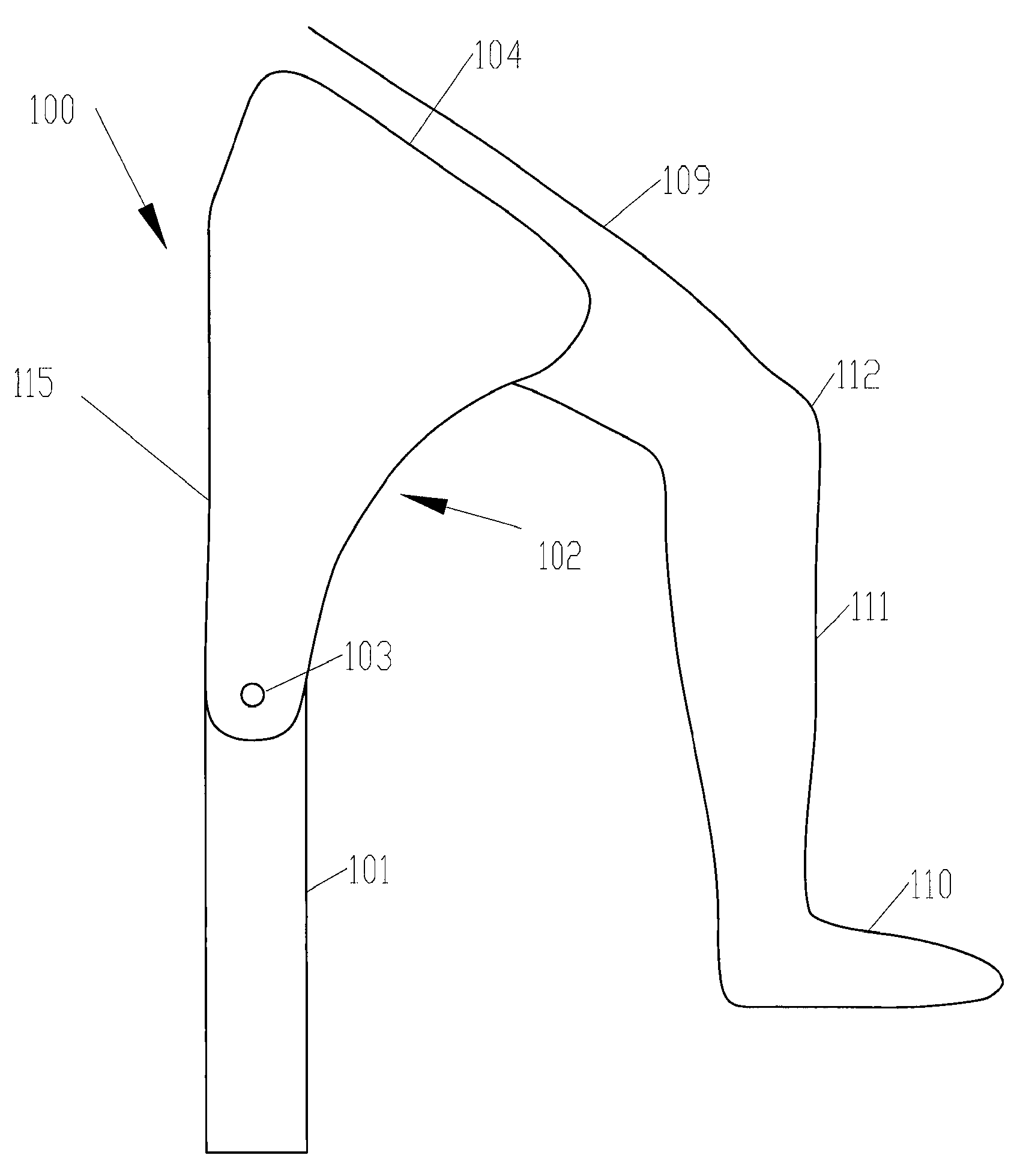
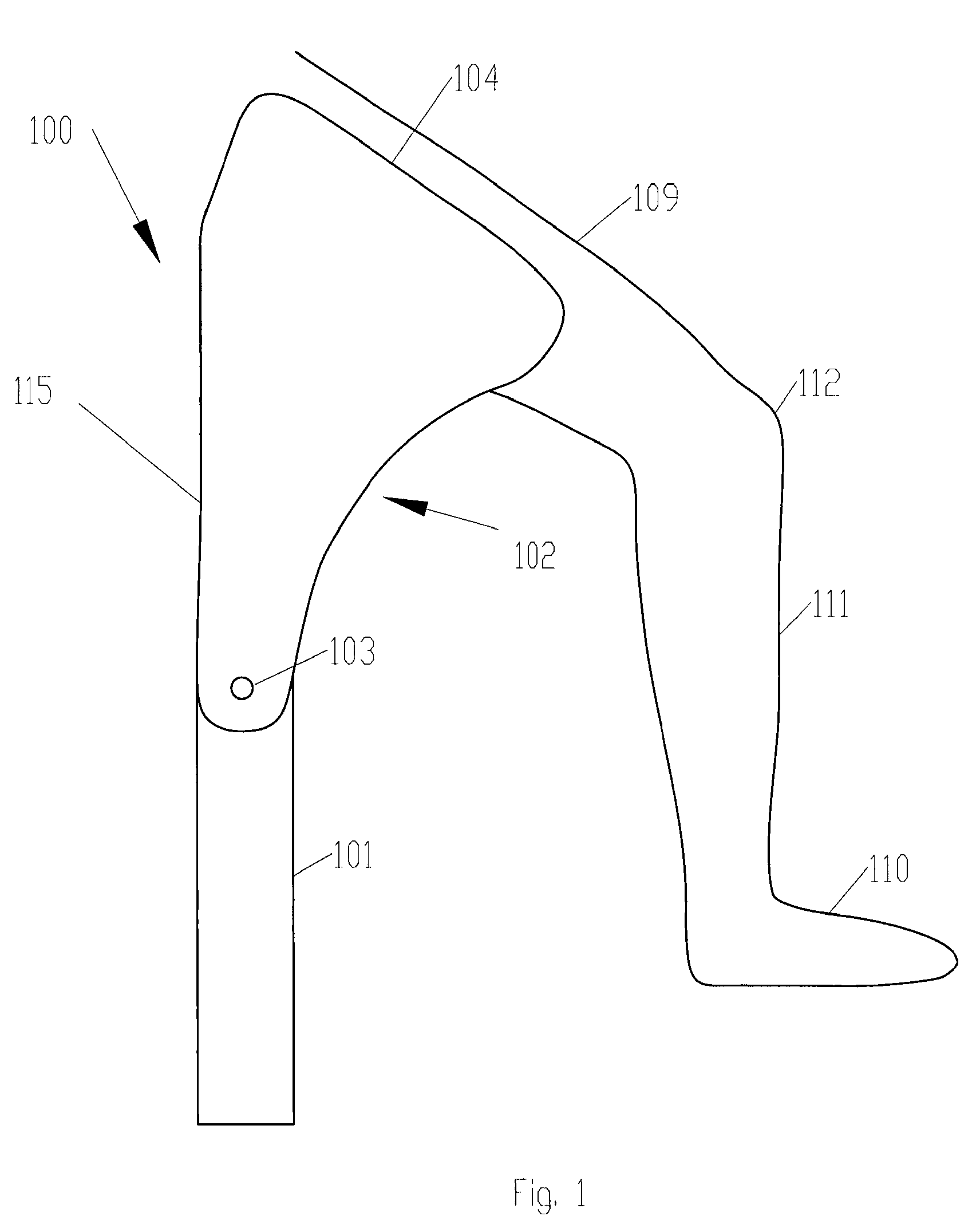
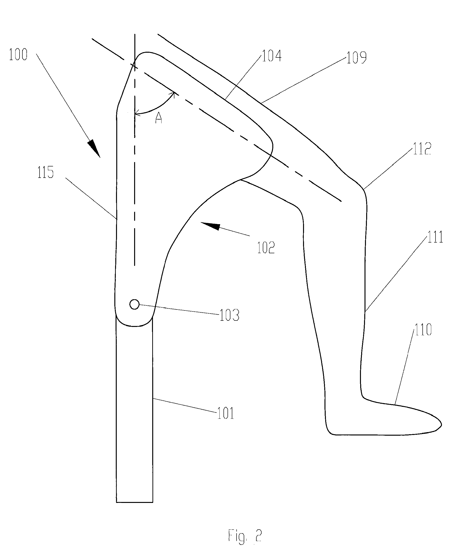
[0030]In accordance with one exemplary embodiment, FIG. 1 is a drawing illustrating a walking assist device 100 having a shank link 101 and a thigh member 102 rotatably connected to each other at a knee mechanism 103. Thigh member 102 is configurable to be in contact with the person's thigh 109. In operation, when walking assist device 100 is in contact with the ground through its shank link 101 (i.e., stance phase), knee mechanism 103 is resisting the motion (i.e., rotation) of shank link 101 relative to thigh member 102, thereby preventing the person's foot 110 from contacting the ground and reducing the ground reaction force entering the person's foot 110.

[0031]In some embodiments, as shown in FIG. 1, walking assist device 100 operates such that when shank link 101 is not in contact with the ground (i.e., swing phase), the resistance of knee mechanism 103 to the motion (i.e., rotation) of shank link 101 relative to thigh member 102 is less than the resistance of knee mechanism 10...


PUM


Abstract

A walking assist device, which is to be worn on a person's leg, includes a shank link, a thigh member, and a knee mechanism. The thigh member is in contact with the person's thigh when the device is worn on the person's leg. The knee mechanism rotatably connects the shank link to the thigh member. When the shank link is in contact with the ground, the knee mechanism is configured to resist the rotation of the shank link relative to the thigh member to prevent the person's foot from contacting the ground and reduces ground reaction forces entering the person's foot.

Description

CROSS-REFERENCE TO RELATED APPLICATIONS[0001]This application claims the benefit of U.S. Provisional Application No. 61 / 060,791, entitled EXTERNAL HUMAN ASSIST DEVICE FOR THOSE WITH LOWER LEG INJURIES, filed Jun. 11, 2008, which is incorporated herein by reference in its entirety for all purposes.BACKGROUND[0002]1. Field[0003]The present application relates generally to walking assist devices that assist in walking post-injury.[0004]2. Related Art[0005]Crutches are medical devices used when a person has an injured leg or is otherwise unable to use his or her leg. Conventional crutches generally have a single degree of freedom and two endpoints. One endpoint contacts the ground, while the other makes contact with some part of the person's upper body, such as the underarm, and is held by the user's hand. Conventional crutches function by allowing users to put their weight into the crutches, bypassing the injured leg entirely. There are many different kinds of crutches currently on the...

Claims


Application Information

Patent Timeline
Patent Type & Authority Patents(United States)
IPC IPC(8): A61F5/00
CPCA61H3/00A61H2201/165A61H2003/005A61H2201/0165
Inventor KAZEROONI, HOMAYOONHAISLIP, SARA MARIEAMES, JONATHANDATTA, ESHA
Owner RGT UNIV OF CALIFORNIA
Why Eureka
Try Eureka