Orthopedic plate for use on a single ray in the midfoot

a single-ray, orthopedic technology, applied in the field of orthopedic plates, can solve the problems of severe fractures and/or dislocations, development of problems, and trauma to the midfoot, and achieve the effects of less damage to the bone, improved compression, and improved pull-out values

Active Publication Date: 2012-09-04
ORTHOHELIX SURGICAL DESIGNS
View PDF28 Cites 57 Cited by
  • Summary
  • Abstract
  • Description
  • Claims
  • Application Information

AI Technical Summary

Benefits of technology

[0010]In accordance with the present invention an orthopedic plate is provided that is a handy and elegant little plate that can be used in place of a compression staple with better pull-out values, improved compression, and less harm to the bone in which it is used. The invention can be used in a wide variety of indications including for example, lapidus bunionenctomy, calcaneolocuboid fusion, talonavicular fusion, MTP fusion, cuboid fracture, metarsocunieform fusion, chevron osteotomy, Naviculocuneioform fusion, Dwyer osteotomy, cotton osteotomy, isolated TMT fusion, Navicular fracture, Evans osteotomy and the previously mentioned Lisfranc fracture. The present invention is further specifically configured for implantation at the mid-foot and more specifically is configured for use in a single ray The plate has a dumbbell or peanut shaped, footprint which consists simply of two rounded tabs along the longitudinal axis of the plate with a narrowed waist section between the tabs. The longer of the two tabs includes a compression slot that extends in a direction and causes compression toward a locking screw hole in the opposing tab. The plate is radiused along the bottom surface along the longitudinal axis of the plate so that the plate forms a section of a cylinder, which is bilaterally symmetrical with respect to a plane passing through the longitudinal axis.

Problems solved by technology

A structural flaw or malfunction in any one part can result in the development of problems, which are manifested in other areas of the body.
The mid-foot is often the subject of trauma such as results from falls, vehicle crashes and dropped objects.
These accidents often result in severe fractures and / or dislocations.
It commonly occurred when a cavalier fell from his horse with his foot caught in his stirrup and resulted in the fracture and dislocation of multiple bones of the midfoot.
Failure to treat such an injury may result in joint degeneration and subsequent damage to the adjacent nerves and blood vessels.
While the use of k-wires, pins, and screws may provide acceptable results for younger and more plastic patients, these methods of fixation are not always satisfactory.

Method used


Image

  • Orthopedic plate for use on a single ray in the midfoot
  • Orthopedic plate for use on a single ray in the midfoot

Examples


Embodiment Construction

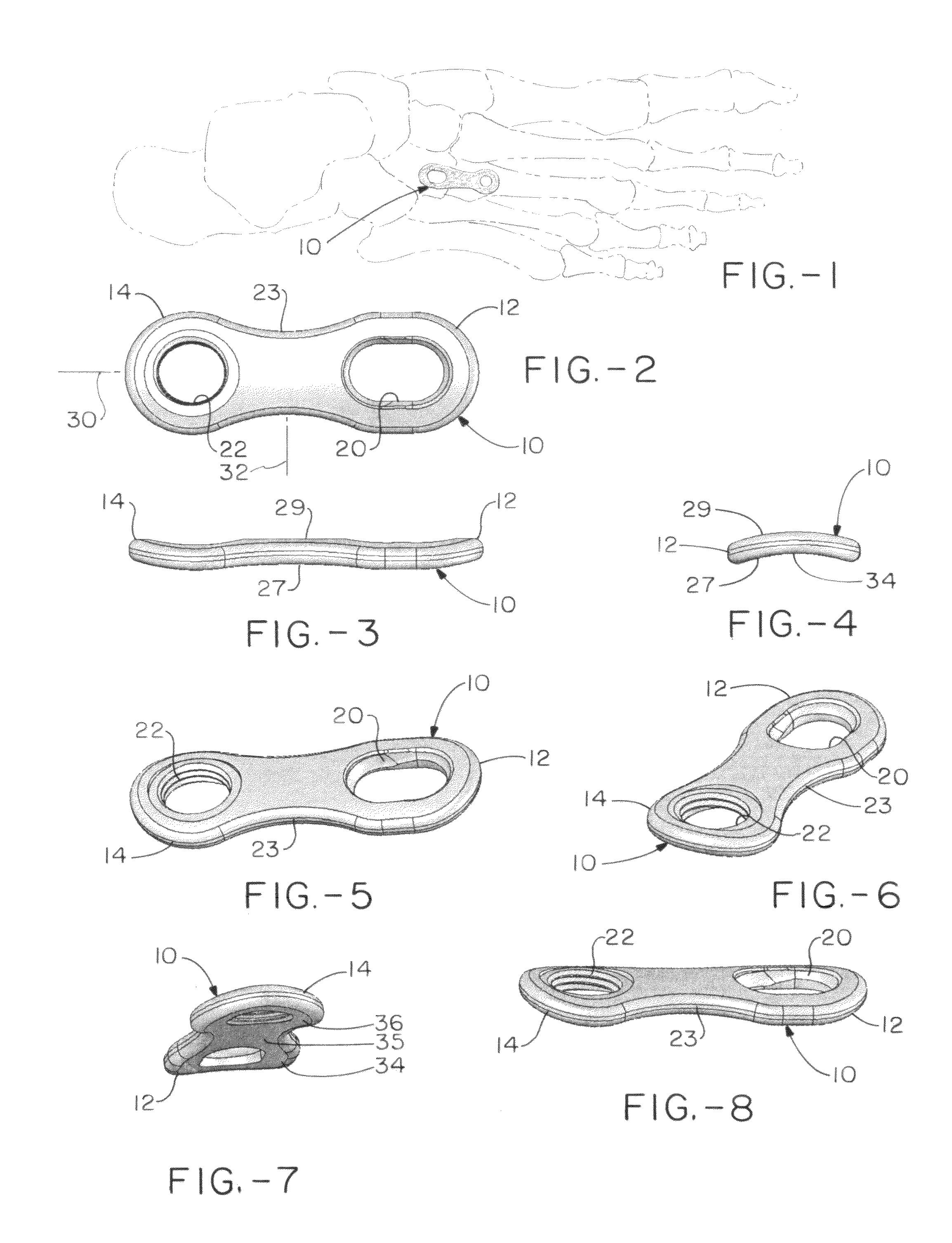
[0019]FIG. 1 shows a skeletal version of a foot from the top (i.e. the dorsal view) with the midfoot plate 10 of the present invention in place between the junction of the third metatarsal and the third cuneiform (i.e. the lateral cuneiform). Thus. FIG. 1 illustrates the plate used in fixation of the bones of the third ray or 3nd TMT (tarso-metatarsal) joint. The plate can also be used for fixation of the first and second ray, that is, for fixation of the 1st TMT joint (1st metatarsal to medial cuneiform) and 2nd TMT joint (2nd Metatarsal to middle or intermediate cuneiform). Similarly, it can be used for fixation of the joints of the other rays, for example where a surgical staple might currently be used.

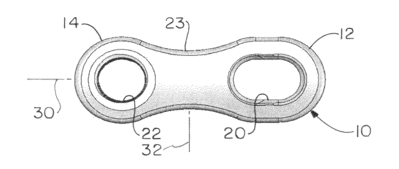
[0020]As viewed from the top in FIG. 2, it can be seen that the plate 10 has two opposing tabs comprising a longer tab 12 and a second shorter tab 14 aligned along the longitudinal axis of the plate. The longer tab 12 includes a compression slot 20, and the other 14 of the pair of ...


PUM


Abstract

An orthopedic plate is specifically configured for implantation at the mid-foot and can be used for a variety of indications. The plate has a set of tabs comprising one longer tab and one shorter tab opposing each other along the length of the plate. In each set of tabs, one tab includes a compression slot that extends in a direction toward a screw hole in the opposing tab.

Description

CROSS-REFERENCE[0001]This is a U.S. patent application of U.S. Provisional Application No. 61 / 066,235 filed on Feb. 19, 2008 for ORTHOPEDIC PLATE FOR USE ON A SINGLE RAY IN THE MIDFOOT which is hereby fully incorporated by reference.FIELD OF THE INVENTION[0002]The present invention relates to an orthopedic plate which is configured for the fixation of a bone or bones of the midfoot including, for example, stabilization of a fracture, dislocation or reconstruction of a deformity.BACKGROUND OF THE INVENTION[0003]Together the foot and ankle have over 25 bones and 33 joints along with more than 100 named muscles, tendons, and ligaments and a network of blood vessels, nerves, all residing beneath a relatively slim covering of soft tissue and skin. Structurally, the foot has three main anatomical regions: the forefoot, the midfoot, and the hindfoot. These parts work together with the ankle, to provide the body with support, balance, and mobility. A structural flaw or malfunction in any on...

Claims


Application Information

Patent Timeline
Patent Type & Authority Patents(United States)
IPC IPC(8): A61B17/80
CPCA61B17/8014A61B17/8061
Inventor KAY, DAVID B.DUCHARME, DUSTINLEITHER, ANDREW J.
Owner ORTHOHELIX SURGICAL DESIGNS
Why Eureka
Try Eureka