Dialysis machine, method of controlling the dialysis machine, and computer program for implementing the control

a dialysis machine and dialysis machine technology, applied in the field of dialysis machines, can solve the problems of valve only being able to be relied on, valves may malfunction, and provide some leakage, so as to reduce labor load, reduce pressure, and less harm

Active Publication Date: 2021-10-05
GAMBRO LUNDIA AB
View PDF42 Cites 0 Cited by
  • Summary
  • Abstract
  • Description
  • Claims
  • Application Information

AI Technical Summary

Benefits of technology

[0005]An object of the invention is to at least alleviate the above stated problem. The present invention is based on the understanding that a valve connected between a disinfectant source and the fluid circuit, although a malfunction of the valve giving some leakage occurs, will not provide any disinfectant to the fluid circuit if connected at a position in the fluid circuit where a pressure gradient is present during treatment taking any leaking disinfectant away from the rest of the fluid circuit. Instead, such leakage will be in the other direction, i.e. either the disinfectant may be more or less diluted by water, which causes significantly less harm since dilution of disinfectant may be detected and the issue of leakage fixed or the disinfectant leak is provided out from the circuit, e.g. via a pipe ending in free air, and no patient is exposed to the disinfectant. “Treatment” should here be construed generously, e.g. including parts of setup before a patient is connected, such as priming, etc., where a patient may be exposed later to substances introduced in the fluid circuit. The inventors have also found that this pressure gradient is provided between a positive pressure, e.g. provided by a pure water inlet of the dialysis machine and / or downstream pumps of the dialysis machine, and a lower pressure present in the disinfectant source and / or pipe(s) ending in free air. Thereby, the disinfectant source need not be disconnected by an operator from the dialysis machine during treatment, whereby labour load may be decreased.

Problems solved by technology

However, as with all components, the valve may malfunction and provide some leakage.
Thus, a valve only cannot be relied on.
The solution is of course safeguarding that no disinfectant can reach the fluid circuit during treatment, but, the operator is given additional manual tasks which is time consuming for the operator and thus less efficient in sense of labour resources.

Method used


Image

  • Dialysis machine, method of controlling the dialysis machine, and computer program for implementing the control
  • Dialysis machine, method of controlling the dialysis machine, and computer program for implementing the control
  • Dialysis machine, method of controlling the dialysis machine, and computer program for implementing the control

Examples


Embodiment Construction

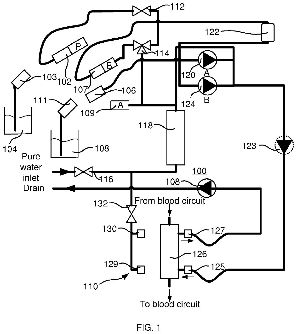
[0027]The aim is to provide a solution which decreases manual tasks for the operator, but still safeguards that no disinfectant can reach the fluid circuit during treatment. A valve for letting disinfectant into a fluid circuit of the dialysis machine prevents this. However, as with all components, the valve may malfunction and provide some leakage. Thus, a valve only cannot be relied on. Therefore, as illustrated in FIG. 1, it is conventional that a disinfectant source is disconnected before treatment commences, and that the connector is normally put in a connector parking position such that the dialysis machine by sensors, which senses the presence of the connector in the parking position, can ascertain that the operator has disconnected the disinfectant source. The solution is of course safeguarding that no disinfectant can reach the fluid circuit during treatment, but, the operator is given additional manual tasks which can be considered less efficient in sense of labour resourc...


PUM

PropertyMeasurementUnit
pressureaaaaaaaaaa
atmospheric pressureaaaaaaaaaa
temperaturesaaaaaaaaaa

Abstract

In an embodiment, a dialysis machine includes a dialyser, a fluid line in fluid communication with the dialyser, an inlet valve enabling fluid to flow into the fluid line towards the dialyser during a dialysis treatment, a disinfectant line connected to the fluid line via a disinfectant valve upstream of the dialyser, the disinfectant valve enabling a disinfectant fluid to be provided to at least part of the fluid line during a disinfection procedure, and a controller programmed to open the inlet valve, while the disinfectant line is connected to a source of disinfectant fluid, to create a positive pressure gradient across the disinfectant valve as fluid flows into the fluid line towards the dialyser, the positive pressure gradient ensuring that the disinfectant fluid from the source of disinfectant fluid does not leak into the fluid line during the dialysis treatment.

Description

PRIORITY CLAIM[0001]The present application is a continuation of U.S. application Ser. No. 15 / 108,907, entitled, “Dialysis Machine, Method of Controlling the Dialysis Machine, and Computer Program for Implementing the Control”, filed Jun. 29, 2016, which is a National Phase of International Application No. PCT / EP2014 / 078401, filed Dec. 18, 2014, which claims priority to Swedish Patent Application No. 1351590-3, filed Dec. 30, 2013, the entire contents of each of which are incorporated herein by reference and relied upon.TECHNICAL FIELD[0002]The present invention generally relates to a dialysis machine, a method of controlling the dialysis machine, and a computer program for implementing the control. In particular, the present invention relates to providing disinfectant for disinfection of the dialysis machine.BACKGROUND[0003]Dialysis machines are routinely rinsed after each use an commonly are disinfected at the end of the day. Disinfection may be using heat or bleach, and is often ...

Claims


Application Information

Patent Timeline
Patent Type & Authority Patents(United States)
IPC IPC(8): A61M1/16A61L2/18A61L2/24A61M39/22
CPCA61M1/169A61L2/18A61L2/24A61M1/168A61M1/1682A61M39/223A61L2202/14A61L2202/24A61M1/1688A61M2205/15A61M2205/3331A61M2205/36A61M2205/702
Inventor HOBRO, STUREJANSSON, OLOFLUNSJO, JAN
Owner GAMBRO LUNDIA AB
Why Eureka
Try Eureka