Biometric device

a biometric and smartcard technology, applied in the field of smartcards, can solve the problems of damage to the fingerprint compared to the fingerprint previously recorded, and achieve the effect of improving the utility of such biometric smartcards

Active Publication Date: 2020-07-28
ZWIPE
View PDF20 Cites 0 Cited by
  • Summary
  • Abstract
  • Description
  • Claims
  • Application Information

AI Technical Summary

Benefits of technology

[0007]This method allows for use of the device even when the fingerprint, thumbprint, or other biometric scan is not a perfect match. This can occur, for example in the case of a fingerprint, when the bearer cuts or burns their finger, leading to damage that changes in the fingerprint compared to the fingerprint previously recorded on the device.
[0013]The first action or set of actions preferably results in less harm than the second action or set of actions, were it or they to be carried out fraudulently. That is to say, lower-security actions may be permitted to a bearer in the event of damage or the like to their body affecting biometric scans, so that the user's device is not entirely disabled, whilst restricting access to higher-security functions in order to minimise possible fraudulent use of the device by an unauthorised person having a similar biometric scan.
[0015]In one embodiment, the first action may be a non-financial action, such as viewing a balance of an account or requesting re-issue of the card, and the second action may be a financial action, such as a payment, a cash withdrawal, or a bank transfer. As above, this reduces the risk that fraudulent financial transactions are carried out, whilst still permitting some use of the device.

Problems solved by technology

This can occur, for example in the case of a fingerprint, when the bearer cuts or burns their finger, leading to damage that changes in the fingerprint compared to the fingerprint previously recorded on the device.

Method used


Image

  • Biometric device
  • Biometric device
  • Biometric device

Examples


Embodiment Construction

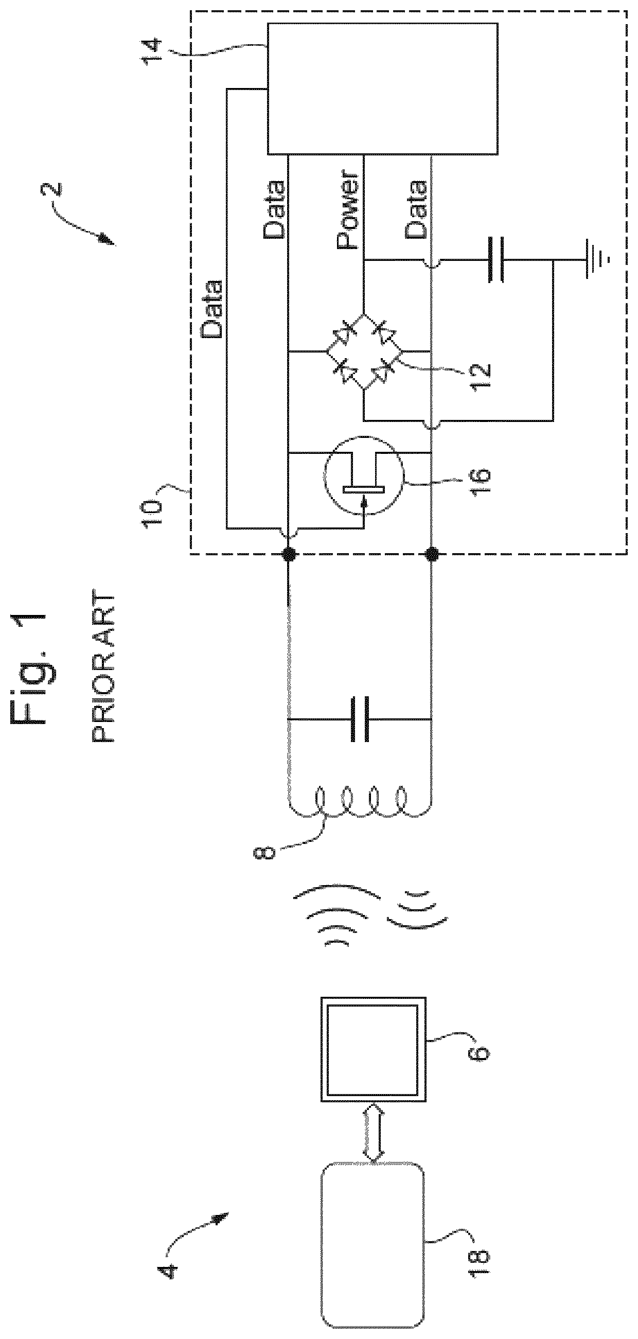
[0054]FIG. 1 shows the architecture of a typical passive smartcard 2. A powered card reader 4 transmits a signal via an antenna 6. The signal is typically 13.56 MHz for MIFARE® and DESFire® systems, manufactured by NXP Semiconductors, but may be 125 kHz for lower frequency PROX® products, manufactured by HID Global Corp. This signal is received by an antenna 8 of the smartcard 2, comprising a tuned coil and capacitor, and then passed to a communication chip 10. The received signal is rectified by a bridge rectifier 12, and the DC output of the rectifier 12 is provided to processing unit 14 that controls the messaging from the communication chip 10.

[0055]A control signal output from the processing unit 14 controls a field effect transistor 16 that is connected across the antenna 8. By switching on and off the transistor 16, a signal can be transmitted by the smartcard 2 and decoded by suitable control circuits 18 in the reader 4. This type of signalling is known as backscatter modula...


PUM


Abstract

A method of using a smartcard may include detecting possible fraudulent use of a biometric sensor embedded within the smartcard and restricting, but not preventing, subsequent use of the smartcard after the possible fraudulent use has stopped. The restriction may include one or more of not permitting the bearer to make an action that they would normally be permitted to make, requiring a higher authorization confidence score than would normally be required before permitting the bearer to perform one or more actions, and requiring the bearer to pass a secondary authorization step before permitting the bearer to perform one or more actions.

Description

TECHNICAL FIELD[0001]The present invention relates to a smartcard including an embedded biometric sensor, and to a method of using such a card to authenticate its bearer.BACKGROUND OF THE INVENTION[0002]The increasing use of electronic cards, such as credit or debit cards, to make payments and cash withdrawals brings with it also an increased risk of fraud. For example, where the user's card is stolen, an unauthorised person may be able to make unauthorised electronic payments or cash withdrawals from the user's bank account or credit provider.[0003]The use of chip-and-PIN protection has decreased the risk of this type of fraud through the use of two-factor authentication, i.e. the possession of the physical card as well as the knowledge of the user's PIN. However, this type of authentication can be inconvenient at times. Furthermore, contactless payment technology is becoming increasing prevalent and often does not require entry of a PIN, meaning that an unauthorised user may still...

Claims


Application Information

Patent Timeline
Patent Type & Authority Patents(United States)
IPC IPC(8): G06F21/00G06F21/45G06F21/32G06K9/00G06K19/07G06Q20/34
CPCG06K9/00006G06F21/32G06K19/0718G06Q20/341G06F21/45G06F2221/2113G06V40/12
Inventor LARSEN
Owner ZWIPE
Why Eureka
Try Eureka