Fire fighter's personal escape system

a personal escape and fire fighter technology, applied in the field of wearable personal escape systems for fire fighters, can solve the problems of increasing the probability of firefighter developing long-term back or leg problems, preventing the firefighter's free delivery, and preventing the firefighter from accomplishing his or her work, so as to achieve a high rate of controlled descent and adjust the descent rate

Active Publication Date: 2012-09-11
BOTTI CHARLES CHRISTOPHER
View PDF30 Cites 8 Cited by
  • Summary
  • Abstract
  • Description
  • Claims
  • Application Information

AI Technical Summary

Benefits of technology

[0027]The present invention discloses a lightweight wearable fire fighter's escape system which allows reliable and rapid escape of a fire fighter from elevated locations in high-rise or multi-floor buildings. This system facilitates a fifty (50) foot escape distance. A fire fighter wearing the subject escape system can readily escape 50 feet from any point in buildings having varying heights. For example, the escape can be a descent of fifty (50) feet from an 80th floor of a building, so that the fire fighter can gain safety on a lower floor, such as the 75th floor. In addition, the fire fighter may choose to descend with no reduction in descent speed or at a desirable descent speed by activating a friction generating mechanism. The wearable escape system incorporates a heat resistant high strength rope.

Problems solved by technology

Others disclose wearable systems that are bulky, heavy and unwieldy and therefore prevent a fireman from accomplishing his or her work.
This concentration of weight in the vicinity of the hip, shoulder or leg increases the probability of the firefighter developing long term back or leg problems.
The presence of the knots in the rope prevents its free delivery.
The fireman has to hold the rope by his hand and rest his legs over the knots to climb down, which cannot be accomplished easily by a fireman wearing shoes or boots.
This fire escape apparatus is not a fireman's emergency exit tool since the braking action is not reliably controlled due to the use of two independent braking systems.
The hook is not designed to create a purchase point on commonly available sources.
The friction generated is not controlled and therefore this device does not allow quick exit from a fire situation and is not useful for a fire fighter.
There is no support for the escaping person since there is no support at the end of the rope.
As a consequence, the person attempting to escape may receive a severe fall.
The pay out of the line is resisted by a spring mechanism and the escape is therefore slow.
Moreover, the disclosed receptacle does not provide quick exit of a fire fighter from a fire emergency situation since no escape tool is carried by the fire fighter.
It does not provide quick escape of a fire fighter from a fire situation due to the presence of braking action, which restricts fast movement.
It does not allow quick exit of a fireman from an unsafe situation since the device incorporates a brake, which cannot be disengaged.
The life saving implements do not provide an escape means for a fireman.
The rope does not have a hook capable of multiple anchoring functionality.
The descent rate is merely controlled by the number of times the rope is wrapped around the hook and one of the turns may slip out suddenly decreasing friction providing unreliable descent.
This is a bulky device and is not worn by a fire fighter for escape from emergency situation.
The rope is not integrally associated with a hook and cannot be readily used by a fireman for escape from a burning inferno.
The repel rescue system does not have a hook for creating attachment point readily.
The fire escape device is unsuited for use by a fire fighter.
The descending device does not have a multi-functional hook capable of creating an anchoring point.
Unlike the first end of the rope which has a knot, the second end of the rope may slide back into the bag during descent presenting an unsafe situation since a double strand of the rappel rope is no longer available.
The rope is not orderly packed within the safety harness and may snag or tangle easily.
Since the safety harness is supported on the torso and shoulder straps, it is unsuitable for lowering a person from a height since the safety harness may slip over the head.
This device is not a personal safety system for a fire fighter.
This device does not provide rescue for a fire fighter from a height.
Moreover, the pay out of the rope is jerky and the descent of the user is unpredictable in spite of the friction generation rods.

Method used


Image

  • Fire fighter's personal escape system
  • Fire fighter's personal escape system
  • Fire fighter's personal escape system

Examples


Embodiment Construction

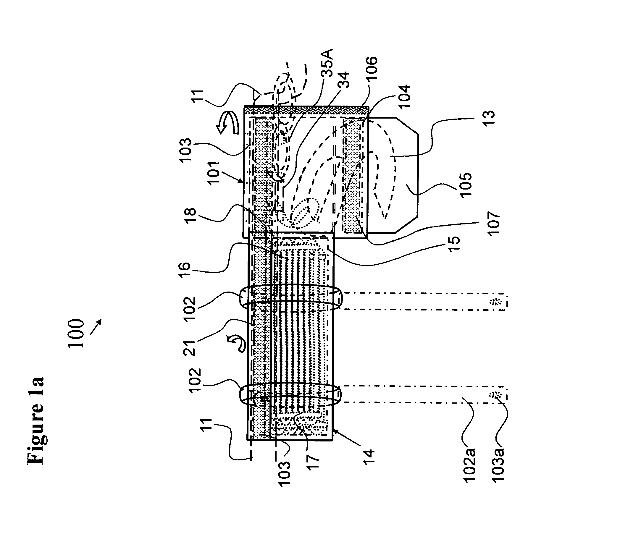
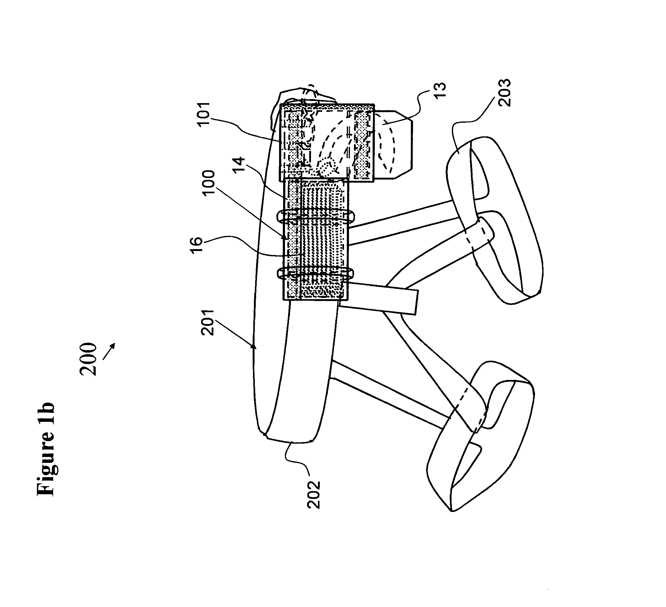
[0061]This invention relates to a lightweight personal escape system worn and used by a fire fighter during an emergency situation. The system provides capability for a descent of approximately 50 feet without having to search for locations that provide basis for attachment of an escape rope. This lightweight system is worn by the fire fighter as an accessory that is securely attached to a belt. The lightweight personal escape system includes benefits emanating from: (i) the location of the rope-carrying pouch, which is located near the lumbar section of the back; and (ii) use of a rope applied in as a single use deployment rope arrangement for real life emergency situations on the job, or multiple use deployment rope arrangement for training courses emulating real life emergency situations. Generally, the lightweight system provides at least one discrete rope pouch, and optionally both a rope pouch and a hook pouch, attached or detached to one another. The optional hook pouch prefe...


PUM


Abstract

A wearable lightweight fire fighter's personal escape system and method includes a rope, having a distal and proximal end, packed within an exterior rope pouch that is appointed to be removably attached to a belt or harness, worn by a fire fighter. The proximal end of the rope exits through an opening in the exterior / outer rope pouch and is attached directly to a lightweight hook, or optionally enters a belay device. The hook has a sharp point for creating a purchase point on soft surfaces, a hook opening having sufficient diameter to surround radiators, steam pipe and the like, and capture rope that surrounds substantial objects. The hook has a central opening appointed for holding a firefighting tool to aid in creating a substantial object. The fire fighter escapes by creating a purchase point and repelling at a high speed or at a controlled speed by adjusting belay friction.

Description

CROSS-REFERENCE TO RELATED APPLICATIONS[0001]This application is a continuation-in-part of U.S. patent application Ser. No. 11 / 407,826, which was filed on Apr. 20, 2006, now U.S. Pat. No. 7,942,241 the disclosure of which is hereby incorporated by reference.BACKGROUND OF THE INVENTION[0002]1. Field of the Invention[0003]The present invention relates to a lightweight wearable personal escape system and a method therefor for providing escape capability for fire fighters from multi-floor or high-rise buildings; and more particularly, to a personal escape system that provides a lightweight hook carried on the right or left hip appointed to engage with a substantial object and being attached to a high strength heat resistant rope carried on the lumbar section of the back organized into a plurality of segments disposed in a discrete relationship with each other to provide for reliable, tangle-free, high speed deployment so that a fire fighter can escape a perilous situation with rapid des...

Claims


Application Information

Patent Timeline
Patent Type & Authority Patents(United States)
IPC IPC(8): A62B1/00
CPCA62B1/16
Inventor BOTTI, CHARLES CHRISTOPHER
Owner BOTTI CHARLES CHRISTOPHER
Why Eureka
Try Eureka