Fire fighter's personal escape system

a personal escape and fire fighter technology, applied in the field of wearable personal escape systems for fire fighters, can solve the problems of preventing the free delivery of firefighters, preventing firefighters from accomplishing their work, and unable to achieve the work of firefighters wearing shoes or boots, so as to facilitate the escape distance of fifty (50) feet, high strength, and reliable and rapid escape of firefighters

Inactive Publication Date: 2007-10-25
BOTTI CHARLES CHRISTOPHER
View PDF26 Cites 26 Cited by
  • Summary
  • Abstract
  • Description
  • Claims
  • Application Information

AI Technical Summary

Benefits of technology

[0026] The present invention discloses a lightweight wearable fire fighter's escape system which allows reliable and rapid escape of a fire fighter from elevated locations in high-rise buildings. This system facilitates a fifty (50) foot escape distance. A fire fighter wearing the subject escape system can readily escape 50 feet from any point in buildings having varying heights. For example, the escape can be a descent of fifty (50) feet from an 80th floor of a building, so that the fire fighter can gain safety on a lower floor, such as the 30th floor. In addition, the fire fighter may choose to descend with no reduction in descent speed or at a desirable descent speed by activating a friction generating mechanism. The wearable escape system incorporates a heat resistant high strength rope. The outside of the rope is fabricated from Kevlar™, an aramid fiber. While the inside of the rope is fabricated from Vectran. The rope is folded in a ‘parachute rope-like, organized manner into parallel segments within a heat shrink inner pouch which is entirely contained in a heat resistant outer pouch appointed to be attached to a belt or harness worn by the fire fighter. The parallel segments are restrained by a rope loop, which breaks as the rope is deployed. This organized arrangement of the rope allows high-speed deployment of the rope without rope tangling. In the first embodiment, the proximal end of the rope is attached to a lightweight high strength hook with a sharp point and the distal end is held in place within the inner pouch. In the second embodiment, the rope passes through a belay or friction-generating element, which is attached to the belt carrying the outer pouch by a carabineer or quick link prior to attachment of the rope with the hook. The belt also carries an additional hook pouch appointed to receive the hook. The belt may comprise a waist belt portion acting unilaterally to support the wearer. Alternatively and preferably, the belt has a harness with two straps which function as leg supports so that the belt, together with leg straps, supports the fire fighter properly during descent.

Problems solved by technology

Others disclose wearable systems that are bulky, heavy and unwieldy and therefore prevent a fireman from accomplishing his or her work.
The presence of the knots in the rope prevents its free delivery.
The fireman has to hold the rope by his hand and rest his legs over the knots to climb down, which cannot be accomplished easily by a fireman wearing shoes or boots.
This fire escape apparatus is not a fireman's emergency exit tool since the braking action is not reliably controlled due to the use of two independent braking systems.
The hook is not designed to create a purchase point on commonly available sources.
The friction generated is not controlled and therefore this device does not allow quick exit from a fire situation and is not useful for a fire fighter.
There is no support for the escaping person since there is no support at the end of the rope.
As a consequence, the person attempting to escape may receive a severe fall.
The pay out of the line is resisted by a spring mechanism and the escape is therefore slow.
Moreover, the disclosed receptacle does not provide quick exit of a fire fighter from a fire emergency situation since no escape tool is carried by the fire fighter.
It does not provide quick escape of a fire fighter from a fire situation due to the presence of braking action, which restricts fast movement.
It does not allow quick exit of a fireman from an unsafe situation since the device incorporates a brake, which cannot be disengaged.
The life saving implements do not provide an escape means for a fireman.
The rope does not have a hook capable of multiple anchoring functionality.
The descent rate is merely controlled by the number of times the rope is wrapped around the hook and one of the turns may slip out suddenly decreasing friction providing unreliable descent.
This is a bulky device and is not worn by a fire fighter for escape from emergency situation.
The rope is not integrally associated with a hook and cannot be readily used by a fireman for escape from a burning inferno.
The repel rescue system does not have a hook for creating attachment point readily.
The fire escape device is unsuited for use by a fire fighter.
The descending device does not have a multi-functional hook capable of creating an anchoring point.
Unlike the first end of the rope which has a knot, the second end of the rope may slide back into the bag during descent presenting an unsafe situation since a double strand of the rappel rope is no longer available.
The rope is not orderly packed within the safety harness and may snag or tangle easily.
Since the safety harness is supported on the torso and shoulder straps, it is unsuitable for lowering a person from a height since the safety harness may slip over the head.
This device is not a personal safety system for a fire fighter.
This device does not provide rescue for a fire fighter from a height.
Moreover, the pay out of the rope is jerky and the descent of the user is unpredictable in spite of the friction generation rods.

Method used


Image

  • Fire fighter's personal escape system
  • Fire fighter's personal escape system
  • Fire fighter's personal escape system

Examples


first embodiment

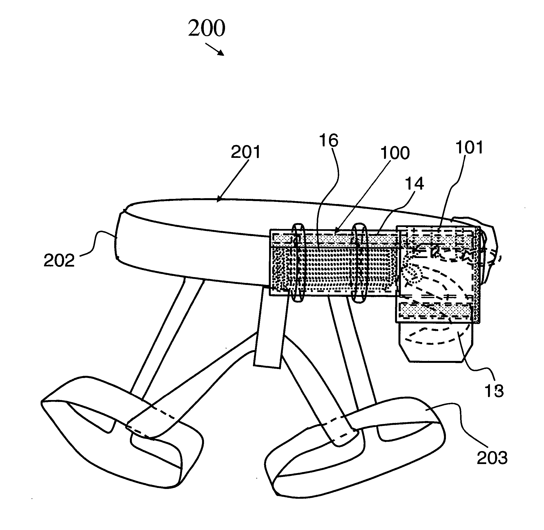
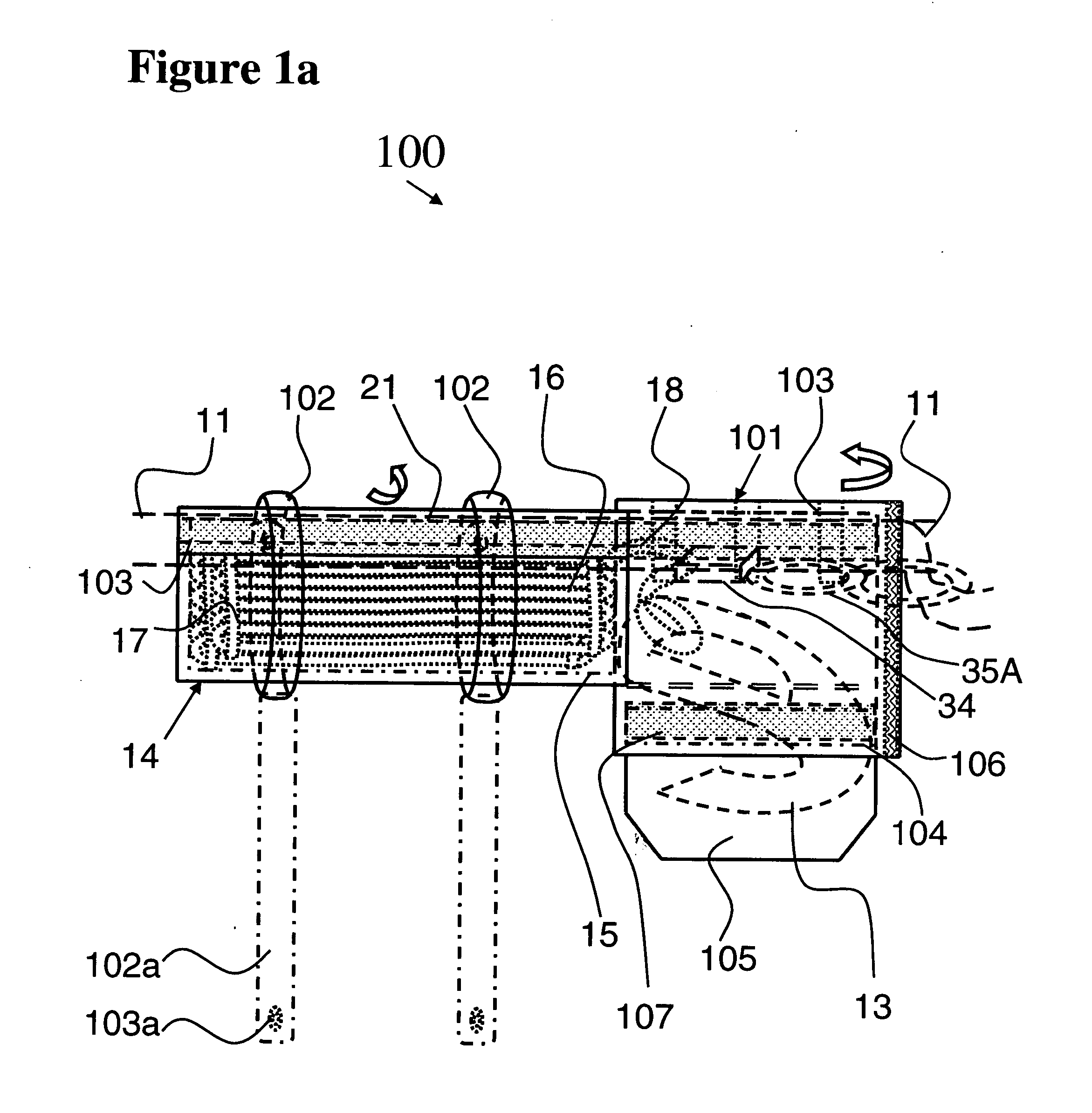
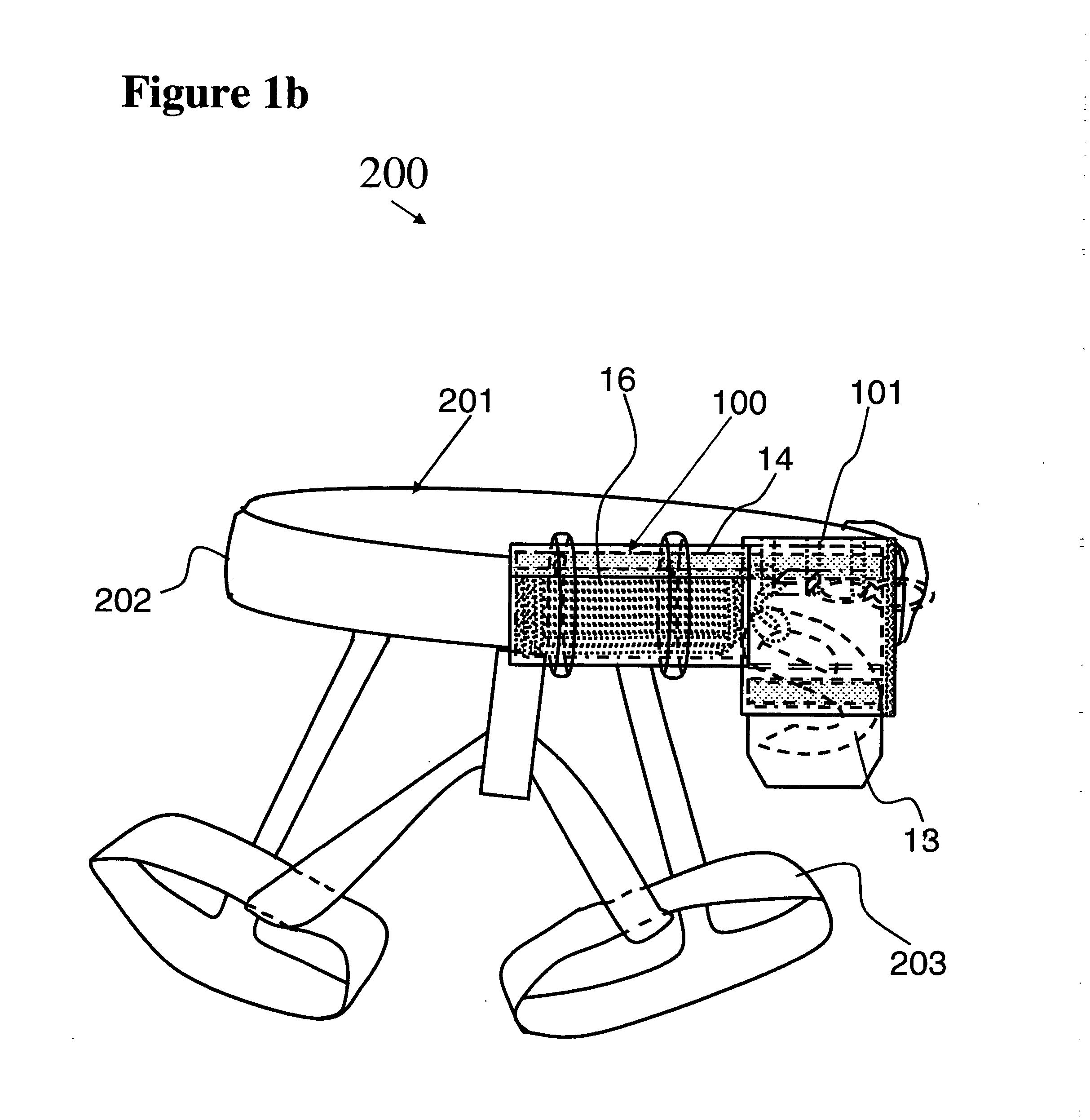
[0075]FIG. 2 illustrates an embodiment of the fire fighter's personal escape system transported by a firefighter, shown at 10. The fire fighter's personal escape system is normally set up on the right side of the fire fighter, but the system is designed to be used on either the right or left side of the fire fighter. Safety harness 11 is shown having leg portions 12. The safety apparatus of the fire fighter's personal escape system is removably attached to the harness 11 by way of attachment means, such as through a snap system, hook and eye, strap system, or the like. As shown, external or outer pouch 14 (along with internal or inner pouch 15 and rope 16) is removably attached to the waist portion of harness 11. Escape hook 13 appends off a proximal end 18 of rope 16. The belay or friction generating device is not included in this first embodiment and the fire fighter descends at the highest speed possible.

[0076]FIG. 3 illustrates the details of the fire fighter's personal escape s...

second embodiment

[0078]FIG. 5 illustrates, at 40, the fire fighter's personal escape system with a belay or friction generating element transported by a firefighter. Safety harness 11 is shown having leg portions 12 and an outer hook pouch 33 to accommodate the escape hook 13, hidden within the outer pouch. A belay or friction device 34 is attached to the safety harness 11 and outer pouch 14 using two easily detachable carabineer type fasteners 35A and 35B. The two carabineers are provided for additional safety, though one carabineer is sufficient to attach the belay or friction-generating element to the belt. The proximal end 18 of the rope 16 passes through the belay or friction device 34 limiting the rate at which the fireman descends. In an emergency, the fireman can release the fasteners 35A and 35B providing rapid decent. The safety apparatus of the fire fighter's personal escape system is removably attached to the harness 11 by way of attachment means, such as through a snap system or the lik...


PUM


Abstract

A wearable lightweight fire fighter's personal escape system and method includes a rope, having a distal and proximal end, organized in parallel segments disposed in an inner pouch. The inner pouch is entirely contained in an outer pouch that is appointed to be removably attached to a belt or harness, worn by a fire fighter. The proximal end of the rope exits through an opening in the inner pouch and outer pouch and is attached directly to a lightweight hook, or optionally enters a belay device. The hook has a sharp point for creating a purchase point on soft surfaces, a hook opening having sufficient diameter to surround radiators, steam pipe and the like, and capture rope that surrounds substantial objects. The hook has a central opening appointed for holding a firefighting tool to aid in creating a substantial object. The fire fighter escapes by creating a purchase point and repelling at a high speed or at a controlled speed by adjusting belay friction.

Description

BACKGROUND OF THE INVENTION [0001] 1. Field of the Invention [0002] The present invention relates to a lightweight wearable personal escape system and a method therefor for providing escape capability for fire fighters from high-rise buildings; and more particularly, to a personal escape system that provides a lightweight hook appointed to engage with a substantial object and being attached to a high strength heat resistant rope organized into a plurality of segments disposed in a discrete substantially parallel relationship with each other to provide for reliable tangle free high speed deployment so that a fire fighter can escape a perilous situation with rapid descent. [0003] 2. Description of the Prior Art [0004] Many patents address issues related to escaping from elevated locations including high-rise buildings. Some of these patents relate to fixed anchoring systems which an escaping person must attach himself to propel therefrom. Others disclose wearable systems that are bulk...

Claims


Application Information

Patent Timeline
Patent Type & Authority Applications(United States)
IPC IPC(8): A62B35/00
CPCA62B1/16Y10T24/4755Y10T24/45435A62B35/0037Y10T24/4512Y10S24/34F16B45/005F16B45/023F16B45/036
Inventor BOTTI, CHARLES CHRISTOPHER
Owner BOTTI CHARLES CHRISTOPHER
Why Eureka
Try Eureka