Method of driving discharge lamp, driving device, and projector

a technology of driving discharge lamp and driving device, which is applied in the direction of electric variable regulation, process and machine control, instruments, etc., can solve the problems of reducing the reducing the service life of the discharge lamp, so as to prevent uneven deterioration and maintain the effect of a long tim

Inactive Publication Date: 2012-09-11
SEIKO EPSON CORP
View PDF34 Cites 0 Cited by
  • Summary
  • Abstract
  • Description
  • Claims
  • Application Information

AI Technical Summary

Benefits of technology

[0008]An advantage of some aspects of the invention is that it provides a method for driving a discharge lamp, which is capable of suppressing deterioration of illumination and preventing electrodes from wearing off unevenly, such a driving device, and a projector using the same.

Problems solved by technology

For this reason, the luminance of a light source device and a projector may be deteriorated and the lifespan of the discharge lamp may be shortened.
However, in a method of restoring the surface of each electrode, which is worn off, by temporarily increasing a current value, the tip portion of the electrode is temporarily completely melted, and the arc length temporarily rapidly increases.
For this reason, illumination may be deteriorated, and flicker and color irregularity may occur.
In a light source including an auxiliary mirror in order to efficiently converge light to be emitted forward, the electrode on the auxiliary mirror side is excessively deteriorated, and the pair of electrodes are deteriorated unevenly.

Method used


Image

  • Method of driving discharge lamp, driving device, and projector
  • Method of driving discharge lamp, driving device, and projector
  • Method of driving discharge lamp, driving device, and projector

Examples


Embodiment Construction

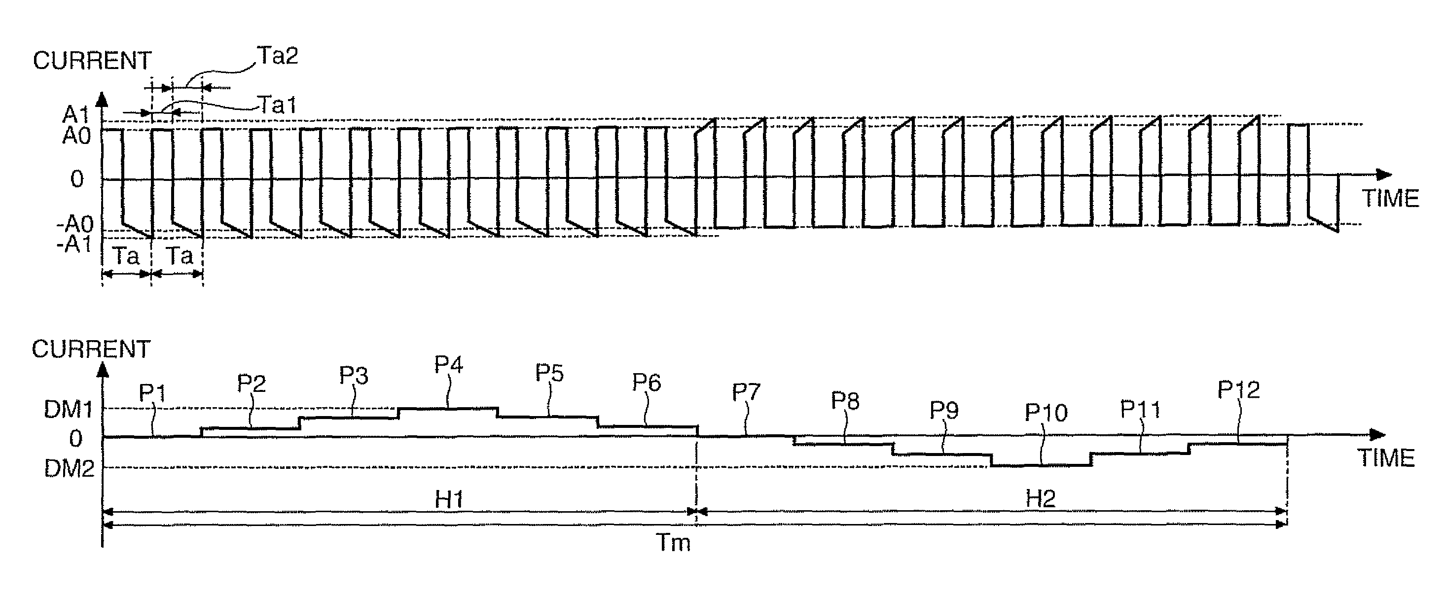
[0030]Hereinafter, a light source device incorporated with a driving device for a discharge lamp according to an embodiment of the invention will be described with reference to the drawings.

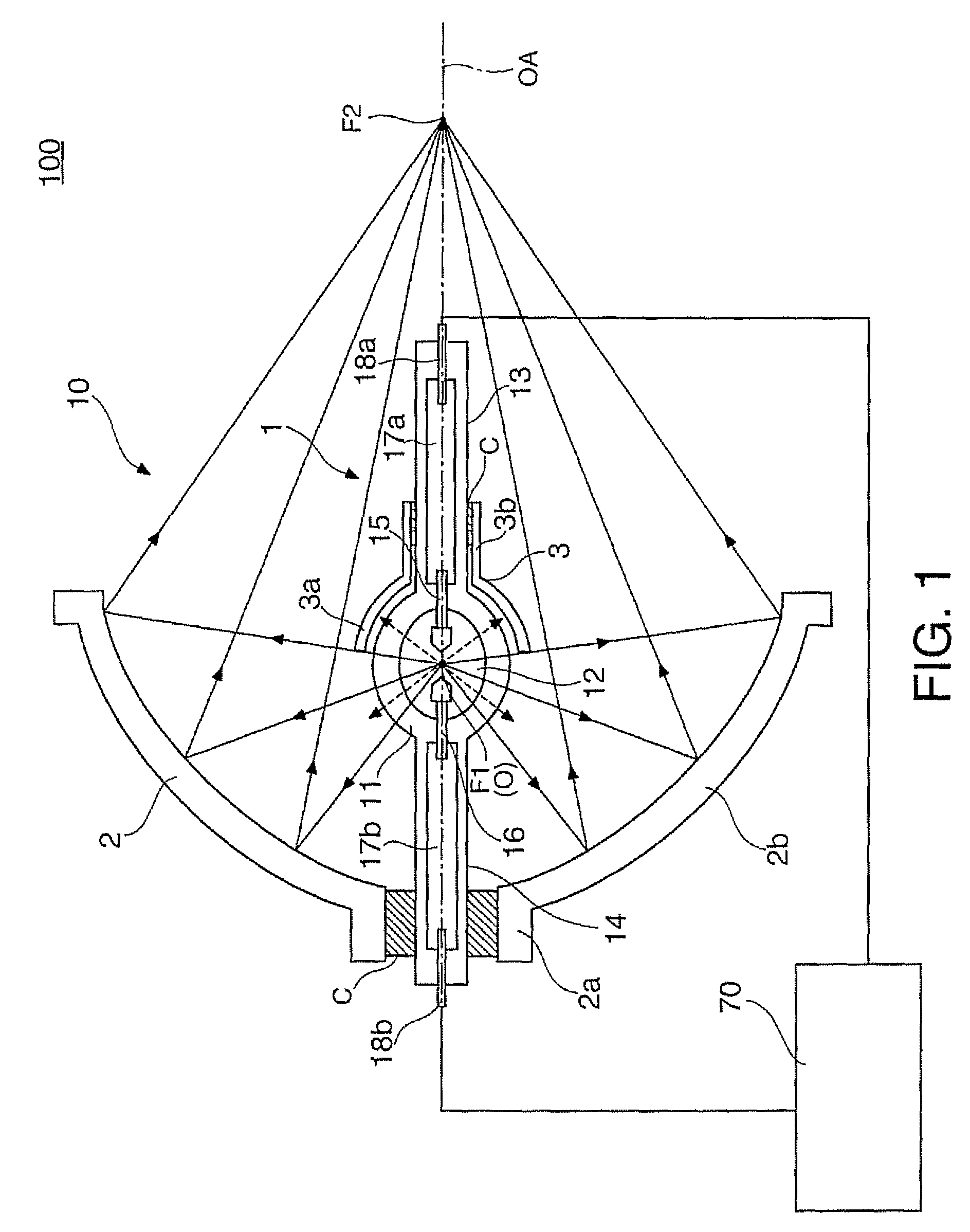
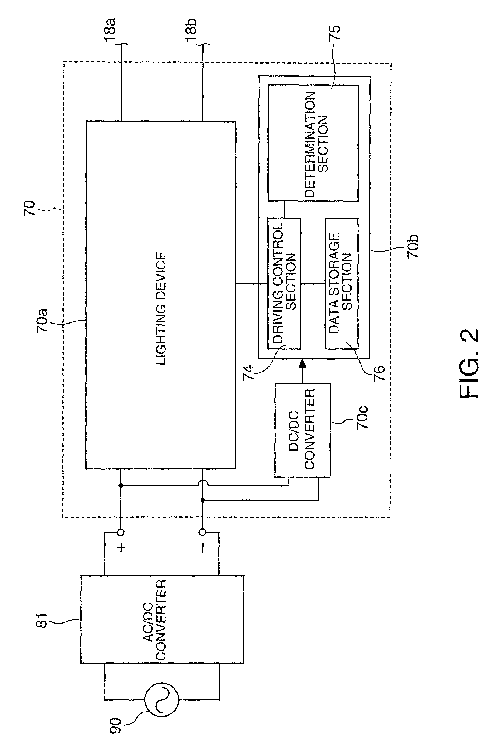
[0031]FIG. 1 is a sectional view conceptually illustrating the structure of a light source device 100. In the light source device 100, a light source unit 10 includes a discharge emission-type light-emitting tube 1 serving as a discharge lamp, an elliptical reflector 2 serving as a primary reflecting mirror, and a spherical auxiliary mirror 3 serving as an auxiliary reflecting mirror. A light source driving device 70 includes, an electrical circuit, serving as a driving device for a discharge lamp, which supplies an AC current to the light source unit 10 so as to cause the light source unit 10 to emit light in a desired state.

[0032]In the light source unit 10, the light-emitting tube 1 is formed of a transmissive silica glass tube having a central portion thereof swollen spherically. The light-em...


PUM


Abstract

A method for driving a discharge lamp having a first electrode and a second electrode includes the steps of, in a situation where a tip portion of the first electrode becomes higher than a tip portion of the second electrode in temperature when power of the same amount is fed to the first and second electrodes during a steady operation, changing a difference between the absolute values of average current values for two polarities during one cycle of the AC current in accordance with a predetermined pattern, and setting an operation time ratio of the first electrode as an anode during one cycle so as to be smaller than an operation time ratio of the second electrode as an anode during one cycle.

Description

BACKGROUND[0001]1. Technical Field[0002]The present invention relates to a method for driving a discharge lamp having a pair of electrodes, a driving device, and a projector including a light source incorporated with such a discharge lamp.[0003]2. Related Art[0004]The state of a discharge emission-type lamp changes in accordance with an operating time, and in particular, electrodes wear off while the lamp is being lighted and the shapes thereof change as time passes. For example, if a plurality of protrusions are grown from the tip portions of the electrodes, and the body portions of the electrodes wear off irregularly, the start point of arc may be moved or the arc length may be changed. For this reason, the luminance of a light source device and a projector may be deteriorated and the lifespan of the discharge lamp may be shortened.[0005]As a method of coping with the wear of the body portions of the electrodes, a technology is known in which a lighting current equal to or more th...

Claims


Application Information

Patent Timeline
Patent Type & Authority Patents(United States)
IPC IPC(8): H05B41/36
CPCH05B41/2928G03B21/2026G03B21/2053Y02B20/208Y02B20/00
Inventor YAMAUCHI, KENTAROTAKEZAWA, TAKESHI
Owner SEIKO EPSON CORP
Why Eureka
Try Eureka