
Spark plug

a plug and spark plug technology, applied in the field of spark plugs, can solve the problems of increasing increasing the wear of the center electrode and the ground electrode, and reducing the contact area between the conductive seal and the center electrode, so as to prevent reduce the energy of the electric charge, the volume of the side-surface seal layer is ensured, and the effect of preventing the wear of the electrod

Active Publication Date: 2019-04-02
NGK SPARK PLUG CO LTD
View PDF12 Cites 0 Cited by
  • Summary
  • Abstract
  • Description
  • Claims
  • Application Information

AI Technical Summary

Benefits of technology

The spark plug effectively prevents electrode wear while maintaining impact resistance and stabilizing resistance values by directing electric charge through the resistor, reducing wear and ensuring reliable contact.

Problems solved by technology

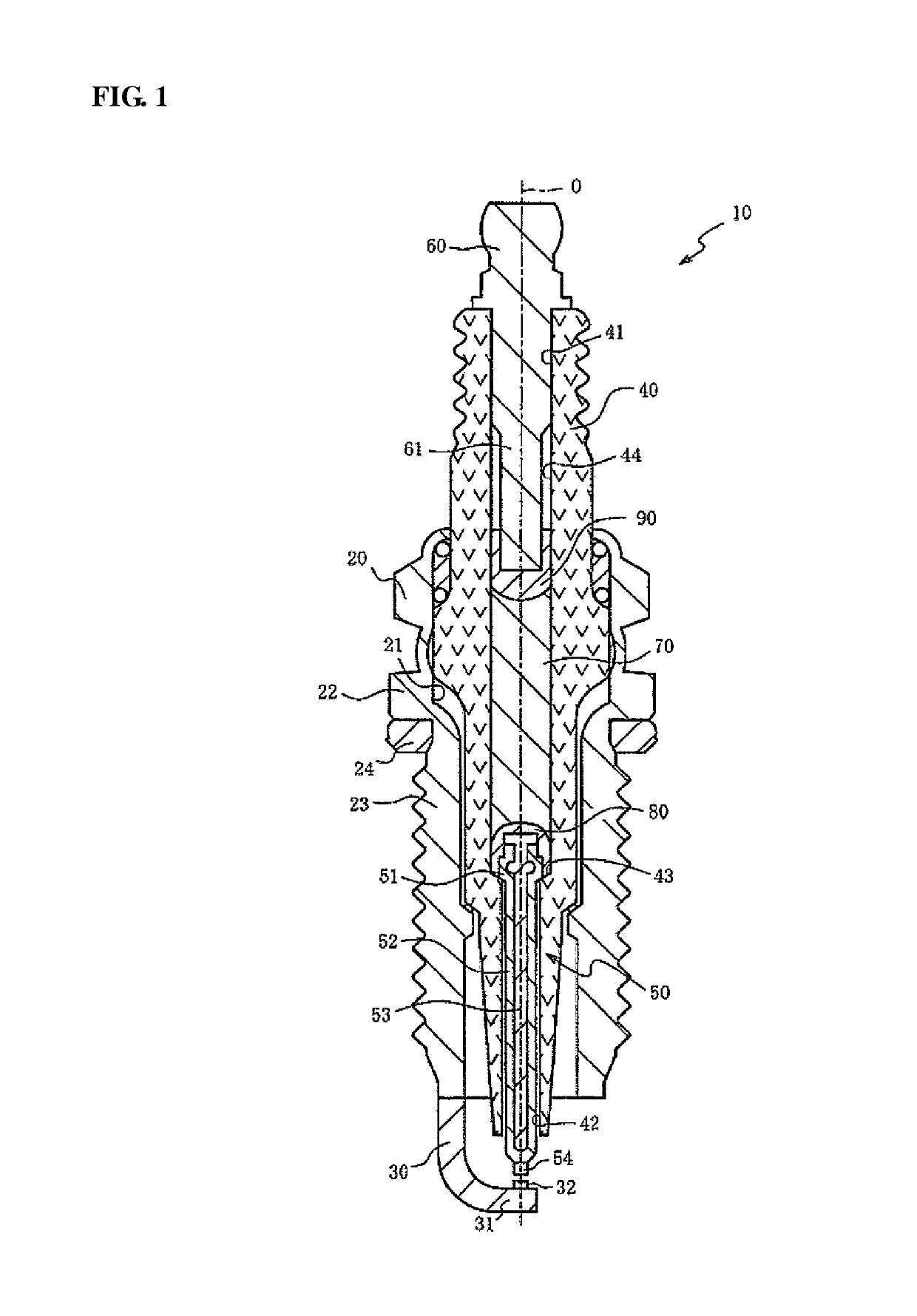
The above conventional spark plug has the problem that, at the time of spark discharge, electric charge accumulated in a parasitic capacitance between the metal shell and the conductive seal or the center electrode moves to the spark gap and accelerates wear of the center electrode and the ground electrode (generically referred to as “electrode wear”).
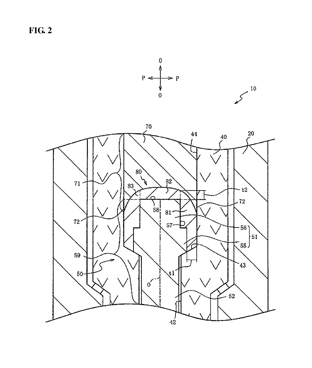
However, this leads to a decrease in the contact area between the conductive seal and the center electrode so that the state of contact between the conductive seal and the center electrode becomes deteriorated by impact or vibration (that is, the spark plug becomes deteriorated in impact resistance).

Method used


Image

  • Spark plug
  • Spark plug
  • Spark plug

Examples


examples

[0084]Spark plugs of Experimental Examples 1 to 7 were prepared, each having the same structure as the spark plug 300 shown in FIG. 5. The spark plugs of Experimental Examples 1 to 7 were common with each other in that the side-surface seal layer 381 was entirely in contact with the whole side surface 57 of the rear end portion 51, but were different from each other in that the thickness t1 of the side-surface seal layer 381 in the axis perpendicular direction was varied within the range of 0.1 μm to 150 μm.

[0085]Impact test was performed on the spark plugs of Experimental Examples 1 to 7 in compliance with Section 7.4 of JIS B8031 (2006). More specifically, each of the spark plugs of Experimental Examples 1 to 7, eight samples for each example, was set to a test machine and subjected to impact at a rate of 400 times per minute for 10 minutes. After that, the occurrence of an anomaly (loosening of the center electrode 50) in each of the eight samples was examined. In each experiment...


PUM


Abstract

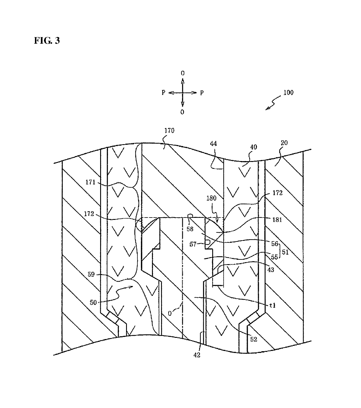
Disclosed is a spark plug capable of preventing electrode wear while ensuring impact resistance. In the spark plug, a conductive seal is arranged between a rear end portion of a center electrode and a resistor within an axial hole of an insulator. The conductive seal includes a side-surface seal layer brought into contact with the whole of a side surface of the rear end portion of the center electrode and having a thickness of 10 μm or larger in an axis perpendicular direction. Assuming that a projection area is defined by projecting the center electrode onto the axial hole in the axis perpendicular direction around a center axis of the spark plug, a contact surface of the resistor brought into contact with the axial hole overlaps at last a part of the projection area.

Description

RELATED APPLICATIONS[0001]This application is a National Stage of International Application No. PCT / JP16 / 83482 filed Nov. 11, 2016, which claims the benefit of Japanese Patent Application No. 2016-027309 filed Feb. 16, 2016, the entire contents of which are incorporated herein by reference.FIELD OF THE INVENTION[0002]The present invention relates to a spark plug with a built-in resistor and, more particularly, to a spark plug capable of preventing electrode wear.BACKGROUND OF THE INVENTION[0003]A spark plug is known having a built-in resistor to suppress radio noise generated by spark discharge (see, for example, Japanese Laid-Open Patent Publication No. 2015-64987). This type of spark plug includes: an insulator formed with an axial hole in which the resistor is arranged; a metal shell partially surrounding an outer circumferential surface of the insulator; a ground electrode joined to a front end of the metal shell; a center electrode inserted in the axial hole of the insulator; a...

Claims


Application Information

Patent Timeline
Patent Type & Authority Patents(United States)
IPC IPC(8): H01T13/20H01T13/34
CPCH01T13/34H01T13/20H01T13/41H01T1/16H01T13/36
Inventor KOBAYASHI, TSUTOMU
Owner NGK SPARK PLUG CO LTD
Learn More