Electricity supply tool holder for machining center

a technology for machining centers and tool holders, which is applied in the direction of manufacturing tools, coupling device connections, inductances, etc., can solve the problems of inability to use tool holders in automatic tool changing (atc) machining centers, increased overall cost of machining centers, and inability to universally use tool holders in other machining centers

Active Publication Date: 2018-01-02
TONG TAI MASCH & TOOL CO LTD
View PDF1 Cites 0 Cited by
  • Summary
  • Abstract
  • Description
  • Claims
  • Application Information

AI Technical Summary

Benefits of technology

[0027]As described above, the electricity supply tool holder for the machining center according to the present invention can not only avoid an electrode wear phenomenon of a contact type electricity supply, but can also be used in a conventional machining center, to be further used in a machining center with an ATC system.

Problems solved by technology

However, since the machining center and the tool holder should both be special specifications, the whole cost of the machining center is increased, the tool holder cannot be universally used in the other machining centers, and they cannot be used in an Automatic Tool Changing (ATC) machining center.

Method used


Image

  • Electricity supply tool holder for machining center
  • Electricity supply tool holder for machining center
  • Electricity supply tool holder for machining center

Examples


Embodiment Construction

[0033]The foregoing objects, features, and advantages adopted by the present invention can be best understood by referring to the following detailed description of the preferred embodiments and the accompanying drawings. Furthermore, the directional terms described in the present invention, such as upper, lower, front, rear, left, right, inner, outer, side, etc., are only directions with reference to the accompanying drawings, so that the used directional terms are used to describe and understand the present invention, but the present invention is not limited thereto. In the drawings, units with similar structures use the same numerals.

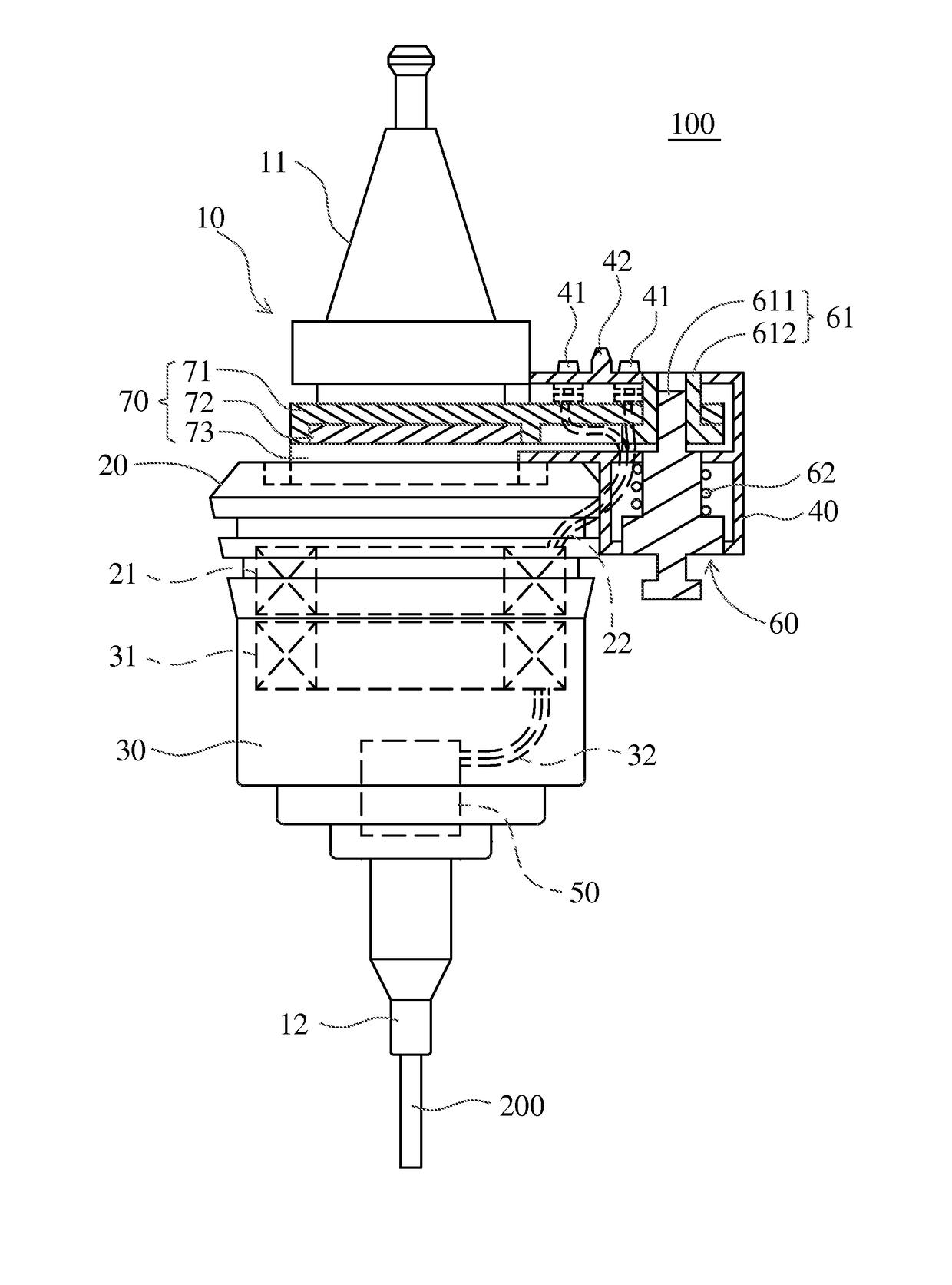
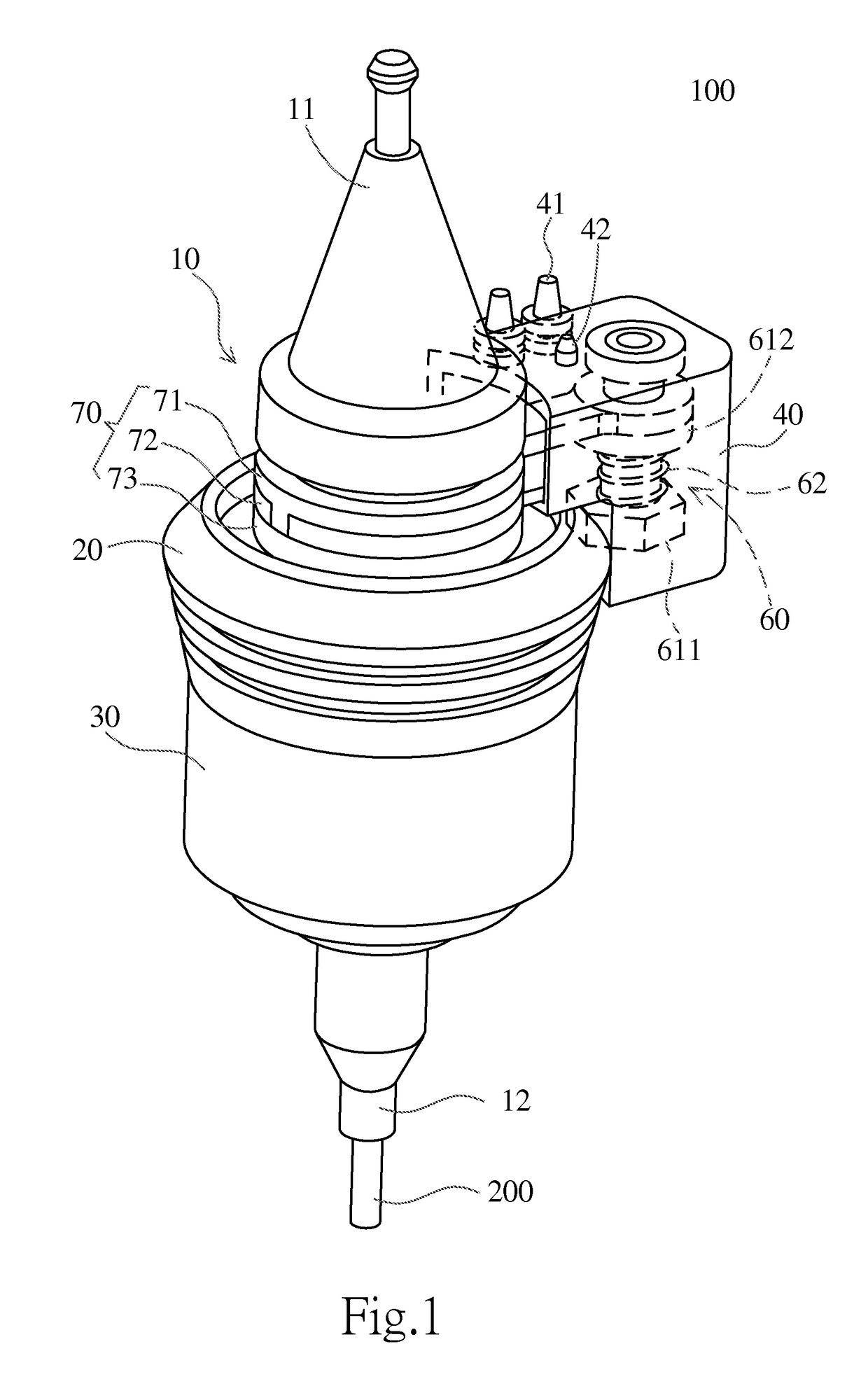
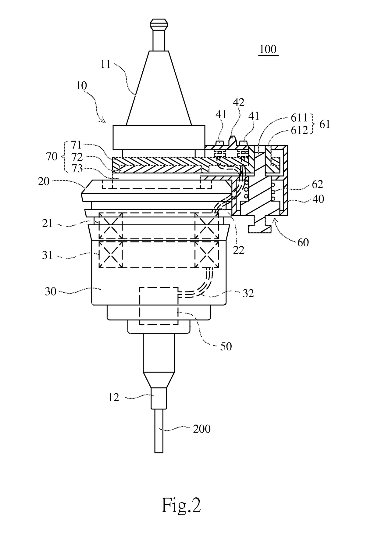
[0034]An electricity supply tool holder for the present invention is used in a machining center, and more particularly in a machining center having a rotating shaft. Refer now to FIGS. 1 and 2, FIG. 1 is a perspective view of an electricity supply tool holder according to a preferred embodiment of the present invention, and FIG. 2 is a side view of th...


PUM

PropertyMeasurementUnit
electric poweraaaaaaaaaa
diameteraaaaaaaaaa
frequencyaaaaaaaaaa

Abstract

An electricity supply tool holder for a machining center is provided, and has: a holder body, a stationary coil portion, a rotating coil portion, a lateral fixing portion, and an electrical machinery. The stationary coil portion is provided with a primary coil therein; the rotating coil portion is correspondingly provided with a secondary coil therein; and the lateral fixing portion is fixed on a side of the stationary coil portion used for removably combining with a machining center. When the tool holder is rotated, an external electric power / signal can be transmitted through the lateral fixing portion to the primary coil, then inducing the secondary coil, then the electric power / signal is transmitted to the electrical machinery. Additionally, the lateral fixing portion can be switched into a locked position to temporarily limit rotation, so that it can be used in a machining center of an Automatic Tool Changing (ATC) system.

Description

FIELD OF THE INVENTION[0001]The present invention relates to an electricity supply tool holder for a machining center, and more particularly to a non-contact type electricity supply tool holder used in an Automatic Tool Changing (ATC) machining center.BACKGROUND OF THE INVENTION[0002]A high frequency vibration cutting is a new type machining technology, and by adding a high frequency vibration into a common cutting tool, an interrupted contact is generated between a cutting tool and a workpiece, and it fundamentally changes the conventional cutting method. This change can solve the problems existing in the conventional cutting technologies, for example the vibration and the heat accumulation during a cutting process or the unstable machining quality, so that the cutting effect is improved.[0003]In a conventional high frequency vibration technology, a high frequency vibration device is disposed inside a tool holder, which is removably mounted on a machining center. Generally, the mac...

Claims


Application Information

Patent Timeline
Patent Type & Authority Patents(United States)
IPC IPC(8): H01F27/42H01F37/00H01F38/00B23Q1/00B23B37/00B23Q3/157H01R13/717
CPCB23Q1/0009B23B37/00B23B2250/16H01R13/7172B23B2270/022B23Q2220/008B23Q3/157
Inventor KAO, HUAI-ENLIN, CHUNG-KUANGOU, JIAN-TZUNGCHEN, HSIN-PAOYEN, JUI-HSIUNG
Owner TONG TAI MASCH & TOOL CO LTD
Why Eureka
Try Eureka