Ignition device

a technology of ignition device and ignition chamber, which is applied in the direction of automatic ignition control, machines/engines, mechanical equipment, etc., can solve the problems of increasing manufacturing cost, increasing the size of the ignition device, and reducing reliability, so as to achieve stable ignition and easy configuration

Active Publication Date: 2018-02-20
DENSO CORP
View PDF16 Cites 2 Cited by
  • Summary
  • Abstract
  • Description
  • Claims
  • Application Information

AI Technical Summary

Benefits of technology

[0011]Accordingly, in light of the background, the present invention has an object to provide an ignition device of an internal combustion engine whose ignition robustness is improved by superimposing discharge currents keeping the same polarity with easy configurations to prevent the blow-off of the discharge, to prevent electrode wear due to re-discharge, and to ensure maintenance of stable discharge.
[0013]According to this disclosure, the secondary current flowing through the secondary coil of the ignition coil is detected, and fed back to control supply and stop of supply of the discharge energy from the auxiliary power source. Thus, with extremely easy configurations, and without being affected by an increase in the second voltage, a difference between devices, aged deterioration, change in discharge environment and the like, the discharge energy can be supplied to the ignition plug, and the secondary current can be kept within a constant range without interruption. Accordingly, a highly reliable ignition device which can maintain the discharge from the auxiliary power source, the discharge being performed after the spark discharge, over an arbitrary period, and thus can realize stabilized ignition.

Problems solved by technology

This results in an increase in manufacturing cost, an increase in size of the device, and a decrease in reliability.

Method used


Image

  • Ignition device
  • Ignition device
  • Ignition device

Examples


first embodiment

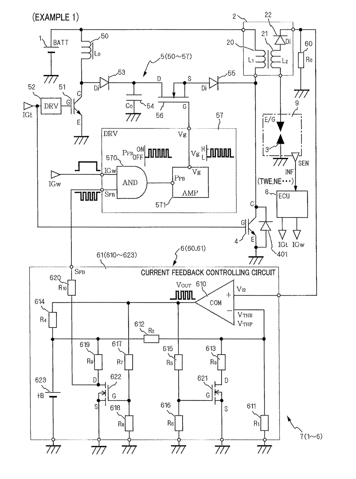
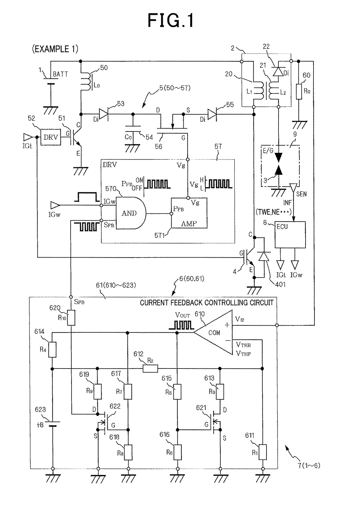
[0042]With reference to FIG. 1, hereinafter is described an ignition device 7 in the present invention. It should be noted that, in this application document, positive and negative signs indicate directions of electric current, and magnitude of electric current is indicated on the basis of the magnitude of an absolute value of electric current. Increase or rise of electric current refers to increase in absolute value of electric current, and decrease or lowering of electric current refers to decrease in absolute value of electric current.

[0043]The ignition device 7 of the present invention is provided to each cylinder of an internal combustion engine 9 and ignites an air-fuel mixture introduced into a combustion chamber, not shown, by generating spark discharge.

[0044]The ignition device 7 includes a direct-current power source 1, an ignition coil unit 2, an ignition plug 3, an ignition switch 4, an auxiliary power source 5, and a secondary current feedback controlling means 6 which ...

second embodiment

[0160]With reference to FIG. 6, hereinafter is described an ignition device 7b according to the present invention.

[0161]It should be noted that the description of configurations similar to the above embodiment is omitted, and that only configurations of a feedback controlling means 6b and a driving driver 57b, which are characteristic of the present invention, are described.

[0162]Example 1 shows the following configuration having hysteresis. That is, the limit changeover switch 621 is driven using the output VOUT of the comparator to change the voltage inputted to the inverting input (−). On the other hand, in present embodiment, the secondary current detection voltage V12 is inputted to the inverting input (−), and the control voltage +B of the control source 623 is proportionally divided by voltage dividing resistors 611b and 612b and inputted to the non-inverting input (+). Further, in present embodiment, the output Vout of the comparator 610 is fed back through the lower limit v...

third embodiment

[0165]With reference to FIG. 7, hereinafter is described an ignition device 7c according to the present invention.

[0166]The present embodiment includes the configurations of the above embodiment, and differs in that the secondary current feedback controlling means 6c includes a secondary current feedback circuit 61c, a discharge blow-off detecting means IGFU62, a secondary current command value calculating means 63, and a secondary current learning means 64. The discharge blow-off detecting means IGFU62 detects the occurrence of discharge blow-off of the secondary current I2 due to in-cylinder airflow in the combustion chamber, and sends a discharge blow-off signal IGF. The secondary current command value calculating means 63 calculates a secondary current target value I2I as a target, according to the operating condition. The secondary current learning means 64 corrects the secondary current target value I2I as a target, according to whether the discharge blow-off has occurred.

[016...


PUM


Abstract

An ignition device at least equipped with a DC power source, an ignition coil unit, a spark plug, an ignition switch, and an auxiliary power source, wherein the auxiliary power source is at least equipped with a discharge energy accumulating means, a discharge switch, and a discharge driver. The ignition device is further equipped with a secondary-current feedback controlling means comprising a secondary current detecting means for detecting a secondary current flowing during the ignition coil unit discharge period, and a secondary current feedback control circuit-for determining an upper limit and a lower limit for the secondary current from binary threshold values, and driving so as to open and close the discharge switch on the basis of the determination results. Furthermore, energy is introduced from the auxiliary power source without switching the polarity of the secondary current.

Description

[0001]This application is the U.S. national phase of International Application No. PCT / JP2014 / 081641 filed Nov. 28, 2014 which designated the U.S. and claims the benefit of priority from earlier Japanese Patent Application No. 2013-246091 filed Nov. 28, 2013, No. 2014-076705 filed Apr. 3, 2014 and No. 2014-189661 filed Sep. 18, 2014, the entire contents of each of which are hereby incorporated by reference.TECHNICAL FIELD[0002]The present invention relates to an ignition device igniting an internal combustion engine, and especially relates to the ignition device including an auxiliary power source ensuring continuous discharge.BACKGROUND ART[0003]PTL1 shows, aside from a usual ignition device, an ignition coil including a DC-DC converter which inputs discharge energy to the ignition coil on the secondary side.[0004]The ignition device of PTL1 extends the discharge continuation period after starting discharge by supplying power to an ignition plug through the secondary coil of the ig...

Claims


Application Information

Patent Timeline
Patent Type & Authority Patents(United States)
IPC IPC(8): F02P15/10F02P5/15F02P3/04F02P3/05F02P5/145F02P17/12F02P9/00
CPCF02P15/10F02P3/0407F02P3/05F02P3/051F02P5/15F02P17/12F02P5/145Y02T10/46F02P9/002F02P9/007F02P3/0442F02P3/0892Y02T10/40
Inventor NAKAYAMA, SATORUTORIYAMA, MAKOTOSUGIURA, AKIMITSUISHITANI, MASAHIROMIZUTANI, ATSUYAANDOH, KOUJIHAYASHI, NAOTODOI, KAORI
Owner DENSO CORP
Why Eureka
Try Eureka