Payment card manufacturing technology

a payment card and manufacturing technology, applied in the field of manufacturing payment cards, can solve the problems of relatively easy manufacturing, easy counterfeiting, and difficulty in making a payment card that is still thin, and achieve the effect of improving the quality of payment cards

Active Publication Date: 2012-09-18
FITBIT INC
View PDF31 Cites 20 Cited by
  • Summary
  • Abstract
  • Description
  • Claims
  • Application Information

AI Technical Summary

Benefits of technology

[0011]An advantage of the present invention is the singulated intermediates after de-molding can be produced and stored in less than maximally secure facilities.
[0012]Another advantage of the present invention is the singulated intermediates after de-molding can be transferred to maximally secure facilities later for finishing with company logos, account data, and personalization.
[0013]A further advantage of the present invention is a payment card is provided that can help protect the user, the merchant and the issuing bank from fraud.
[0014]A still further advantage of the present invention is that a payment card is provided that does not require hardware or software changes to merchant point-of-sale terminals or automatic teller machines.
[0015]Another advantage of the present invention is that a card is provided that can express the personalities of several different kinds of payment cards issued by independent payment processors.
[0016]Another advantage of the present invention is a payment card is provided that can generate a dynamic account number upon each usage, and by doing so, authenticate itself to the transaction infrastructure, whether online or offline.

Problems solved by technology

Such cards were relatively easy to manufacture, and unfortunately very easy to counterfeit.
These all have added to the difficulty in making a payment card that still is thin, flexible, and fits the original dimensions.
Including batteries and electronics into payment cards is especially challenging.
The physical and environmental constraints generally result in a thin electronics package being sandwiched between two plastic sheets and / or embedded in injected plastic.
This generally means that high pressure, high temperature injection molding and lamination methods cannot be used.

Method used


Image

  • Payment card manufacturing technology
  • Payment card manufacturing technology
  • Payment card manufacturing technology

Examples


Embodiment Construction

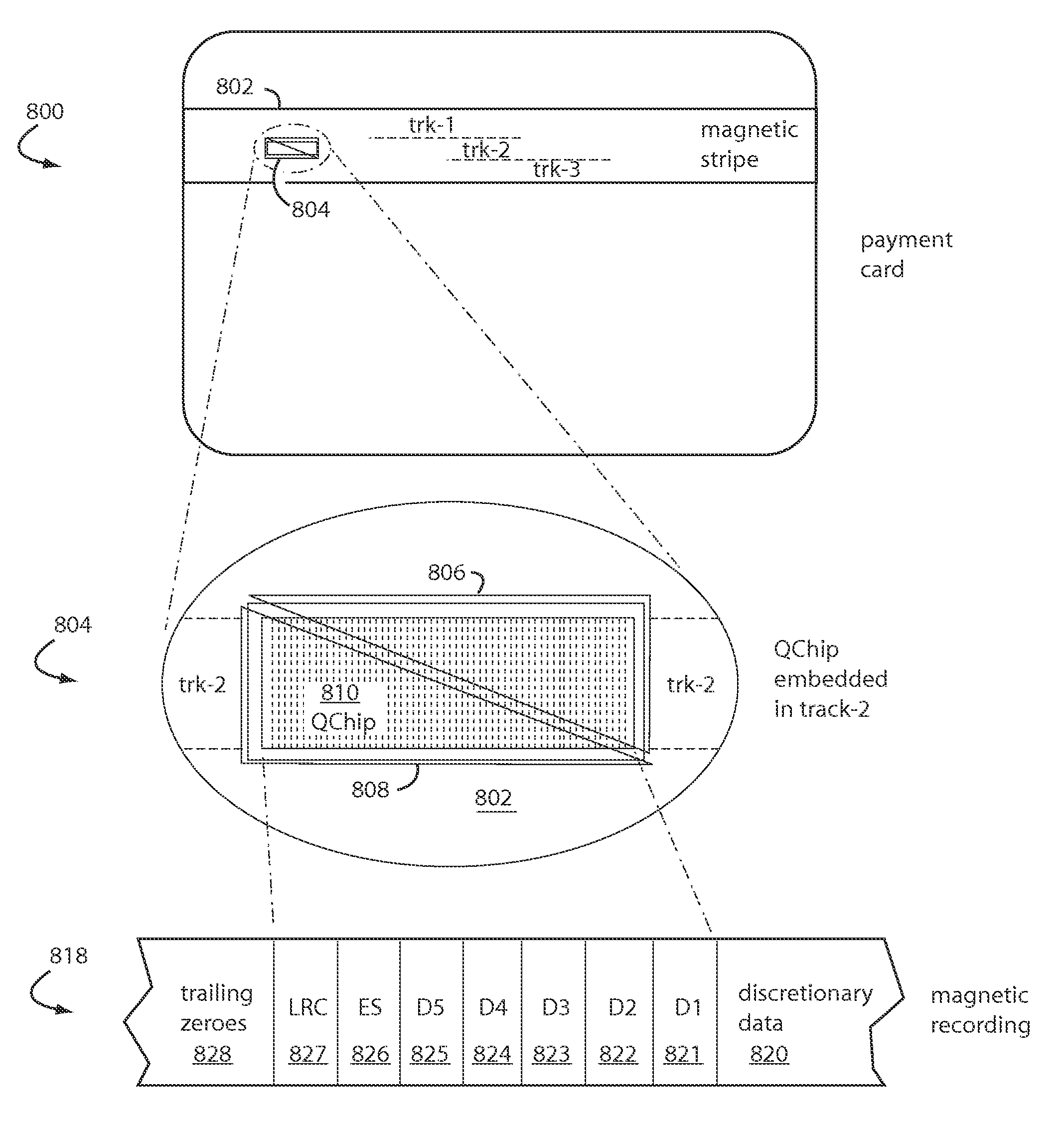
[0030]Embodiments of the present invention produce payment cards with dynamic magnetic stripes.

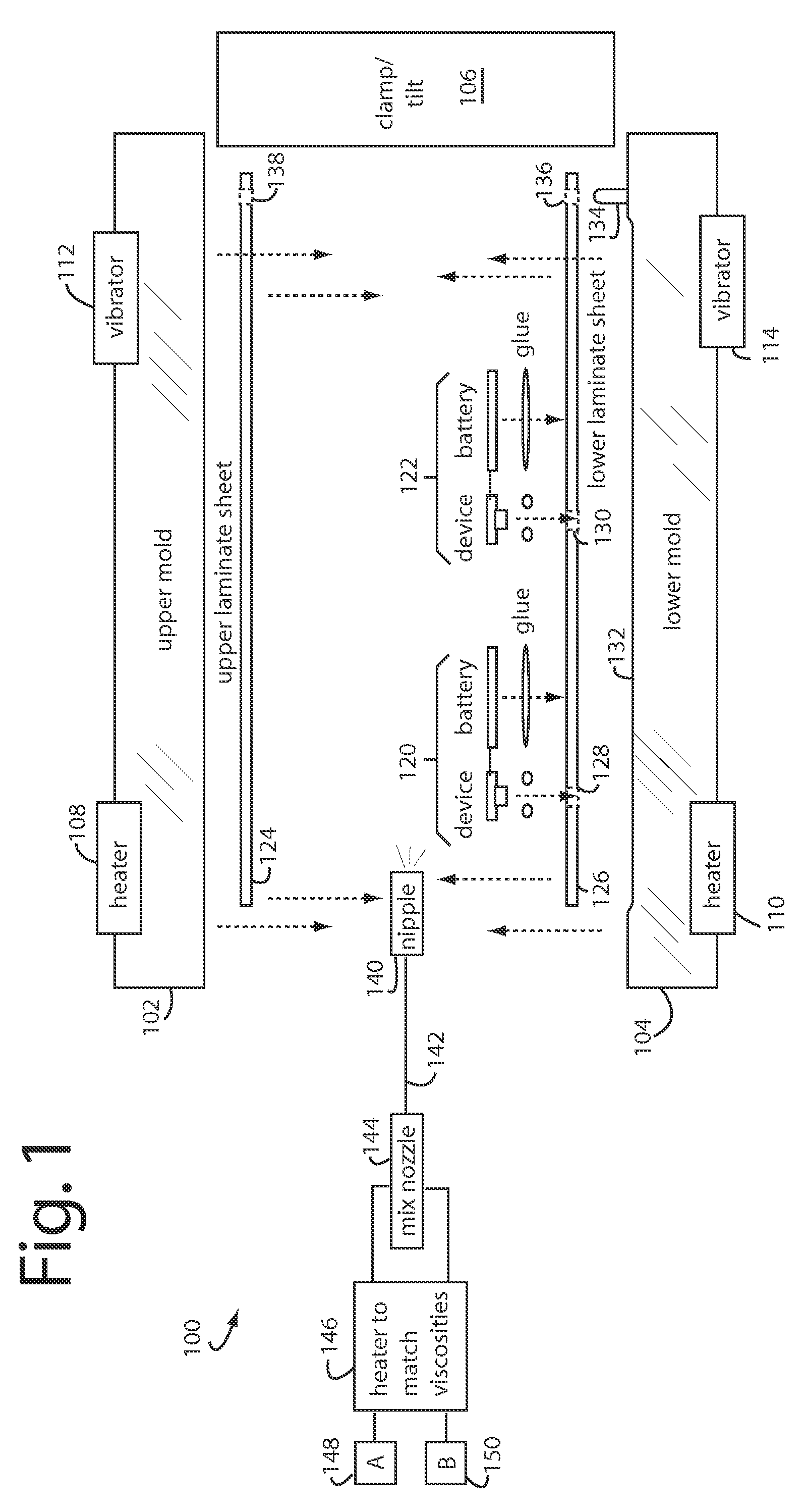
[0031]FIG. 1 illustrates a system embodiment of the present invention for manufacturing payment cards, and is referred to herein by the general reference numeral 100. Such system 100 employs an upper mold 102 that can be opened and hydraulically pressed together with a lower mold 104. Such molds are typically milled from billet aluminum. A mechanism 106 presses the two molds tightly together during plastic injection and can tilt the whole to help evacuate air in the voids displaced by the injected plastic. A pair of heaters 108 and 110 are used to pre-heat the molds so the injected plastic will flow and adhere better. Alternatively, a system of vibrators 112 and 114 can be used during plastic injection to eliminate bubbles.

[0032]In FIG. 1, two subassemblies 120 and 122, for two respective individual payment cards, are shown being sandwiched between an upper laminate sheet 124 and a lower l...


PUM

PropertyMeasurementUnit
adhesionaaaaaaaaaa
magnetic accountaaaaaaaaaa
flexibleaaaaaaaaaa

Abstract

A payment card manufacturing process glues a thin battery and an autonomously reprogrammable magnetic device to the inside surface of one of two outer front and rear laminate sheets. The magnetic device is pressed through a precisely cut rectangular hole provided for it in the rear laminate sheet, and is sealed with a gasket bead. Such magnetic device is critically placed flush in a magnetic stripe area, and the end gaps are such that they will minimize adverse magnetic transitions seen by a reader between the magnetic stripe field and the autonomously reprogrammable magnetic device. The surfaces of the battery, electronics, and laminate sheets, are plasma treated to promote adhesion. These are then all sandwiched together inside a heated mold that is tilted or vibrated just before a two-part polyurethane is injected. Each of the two polyurethane parts is temperature adjusted to match viscosities and thus improve mixing. The liquid polyurethane is injected through a nozzle and manifold to fill all the voids between the laminate sheets, and air escapes or is vacuumed out the top edge of the mold. The polyurethane sets quickly and sheets of sixteen or more payment cards can then be de-molded and singulated.

Description

RELATED APPLICATIONS[0001]This Application is a continuation-in-part of U.S. patent application Ser. No. 11 / 676,285, filed Feb. 17, 2007 now abandoned, and titled PIN-SECURED DYNAMIC MAGNETIC STRIPE PAYMENT CARD. Such and the applications it, in turn, continues from are all incorporated herein by reference.BACKGROUND OF THE INVENTION[0002]1. Field of the Invention[0003]The present invention relates to the manufacturing of payment cards, and in particular how to manufacture payment cards with electronic devices embedded in their magnetic stripes that allow at least a portion of the recorded magnetic account data to be autonomously reprogrammable.[0004]2. Description of Related Art[0005]At one time, credit cards were simple slabs of plastic with user account numbers embossed into them. Merchant embossing machines printed these numbers with carbon paper onto a sales slip that the customer would then sign. Company logos and other color printing were usually included on the outside surfa...

Claims


Application Information

Patent Timeline
Patent Type & Authority Patents(United States)
IPC IPC(8): G06K19/06
CPCG06K19/06196G06K19/077G06K19/083G06Q20/385G07F7/1016
Inventor TSAO, PAULBROWN, KERRY D.
Owner FITBIT INC
Why Eureka
Try Eureka