
Air bag system for vehicle

a technology for air bags and vehicles, which is applied in the direction of vehicular safety arrangements, vehicle components, pedestrian/occupant safety arrangements, etc., can solve the problems of gas leakage from the gap between the vent hole cover and the vent hole, delay in the initial rise of etc., to achieve the effect of facilitating sliding, reducing the inner pressure of the air bag, and ensuring flexibility of blocking member movemen

Inactive Publication Date: 2012-09-18
HONDA MOTOR CO LTD
View PDF16 Cites 12 Cited by
  • Summary
  • Abstract
  • Description
  • Claims
  • Application Information

AI Technical Summary

Benefits of technology

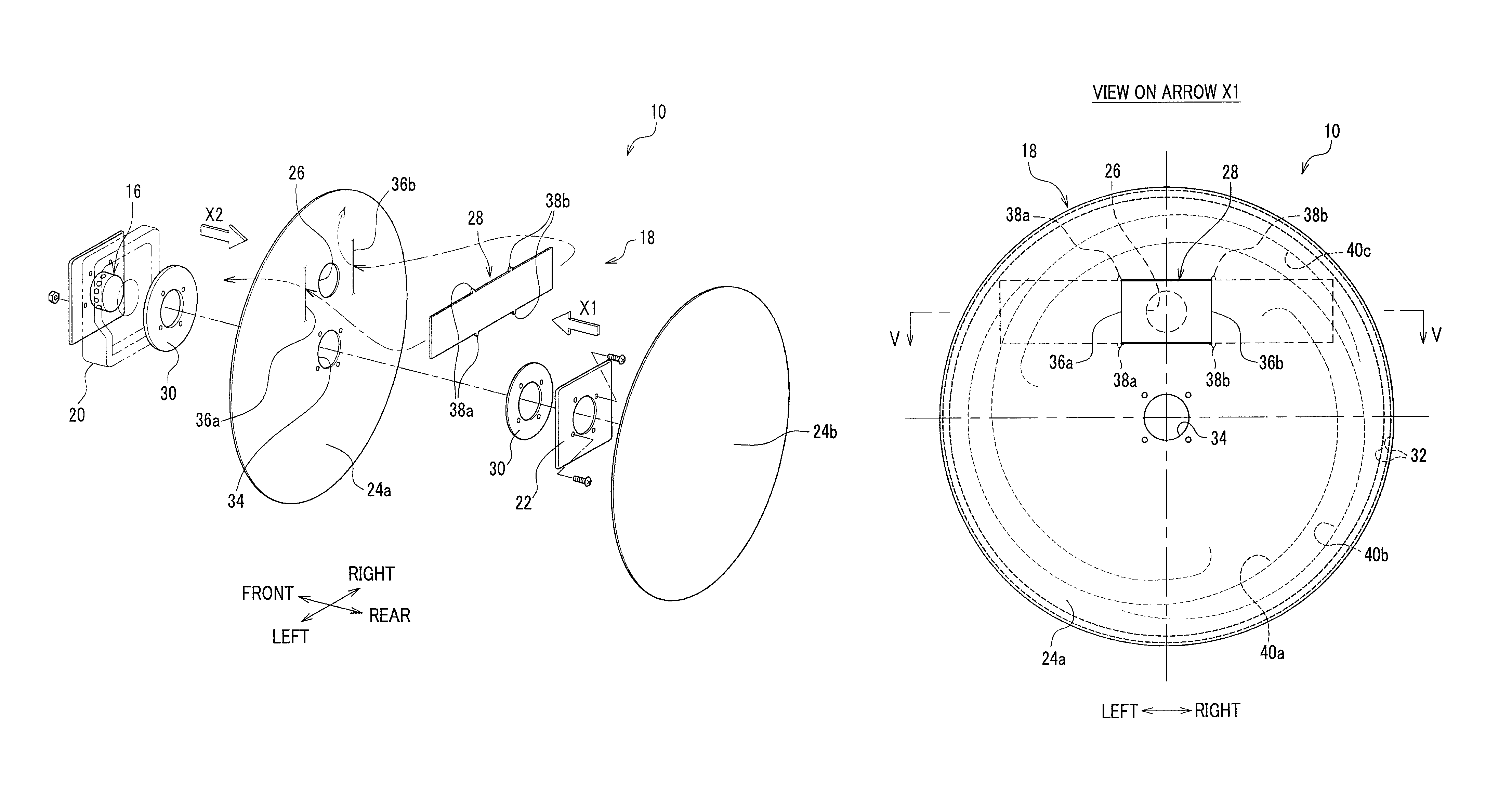
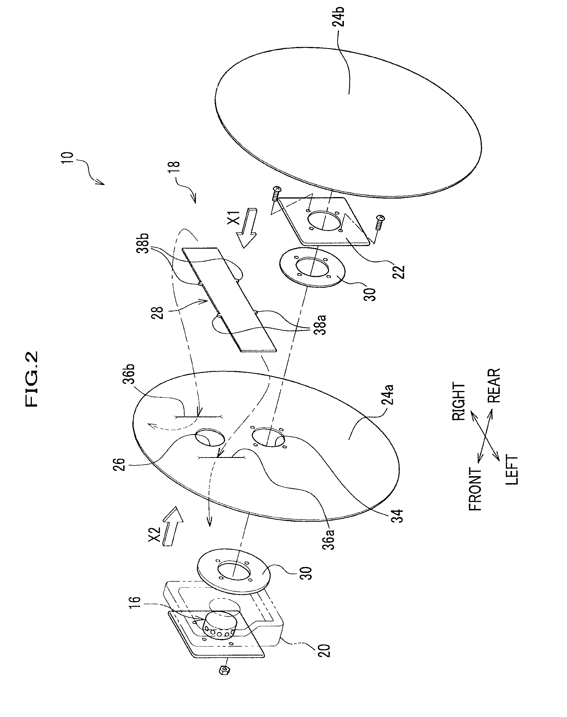
[0011]In order to realize the above object, the present invention provides an air bag system for a vehicle including an air bag in a folded state and installed in a vehicle, the air bag inflating and expanding by a gas supply, and an inflator introducing gas into the air bag. The air bag system further includes a vent hole provided on at least one base fabric piece of the air bag so as to establish a communication between an inside and an outside of the air bag, and discharge gas from the inside toward the outside of the air bag; a blocking member supported on the base fabric piece to block up the vent hole; a guide portion for slidably supporting the blocking member and restricting the position of the blocking member relative to the vent hole; and a sliding resistance increasing portion provided on at least either one of the guide portion and the blocking member, so as to increase a sliding resistance between the guide portion and the blocking member when the blocking member slides.
[0012]The present invention provides the sliding resistance increasing portion on at least one of the guide portion and the blocking portion, so as to increase the sliding resistance between the guide portion and the blocking member when the blocking member slides to release the inner pressure of the air bag. Accordingly, the blocking member is restricted to come apart from the vent hole just for a moment, so that the blocked state of the vent hole can be maintained to prevent the instantaneous gas leakage and make moderate the change in the inner pressure of the air bag.
[0013]As described above, the present invention slightly extends the time period until the inner pressure in the air bag is released right after the blocking member 28 comes in the free state, so that the time while an occupant is being held by the air bag can be longer; accordingly the occupant protection effect can be enhanced much more.

Problems solved by technology

If such a vent hole is unblocked at the very initial state of expansion of the air bag, gas supplied from an inflator is leaked from the vent hole, which causes delay of the initial rise of the inner pressure of the air bag.
However, when the vent hole cover stitched in the vicinity of the outer circumference of the air bag comes released into the free state, the vent hole cover instantaneously comes apart from the vent hole, so that gas leakage from a gap between the vent hole cover and the vent hole may occur.

Method used


Image

  • Air bag system for vehicle
  • Air bag system for vehicle
  • Air bag system for vehicle

Examples


Embodiment Construction

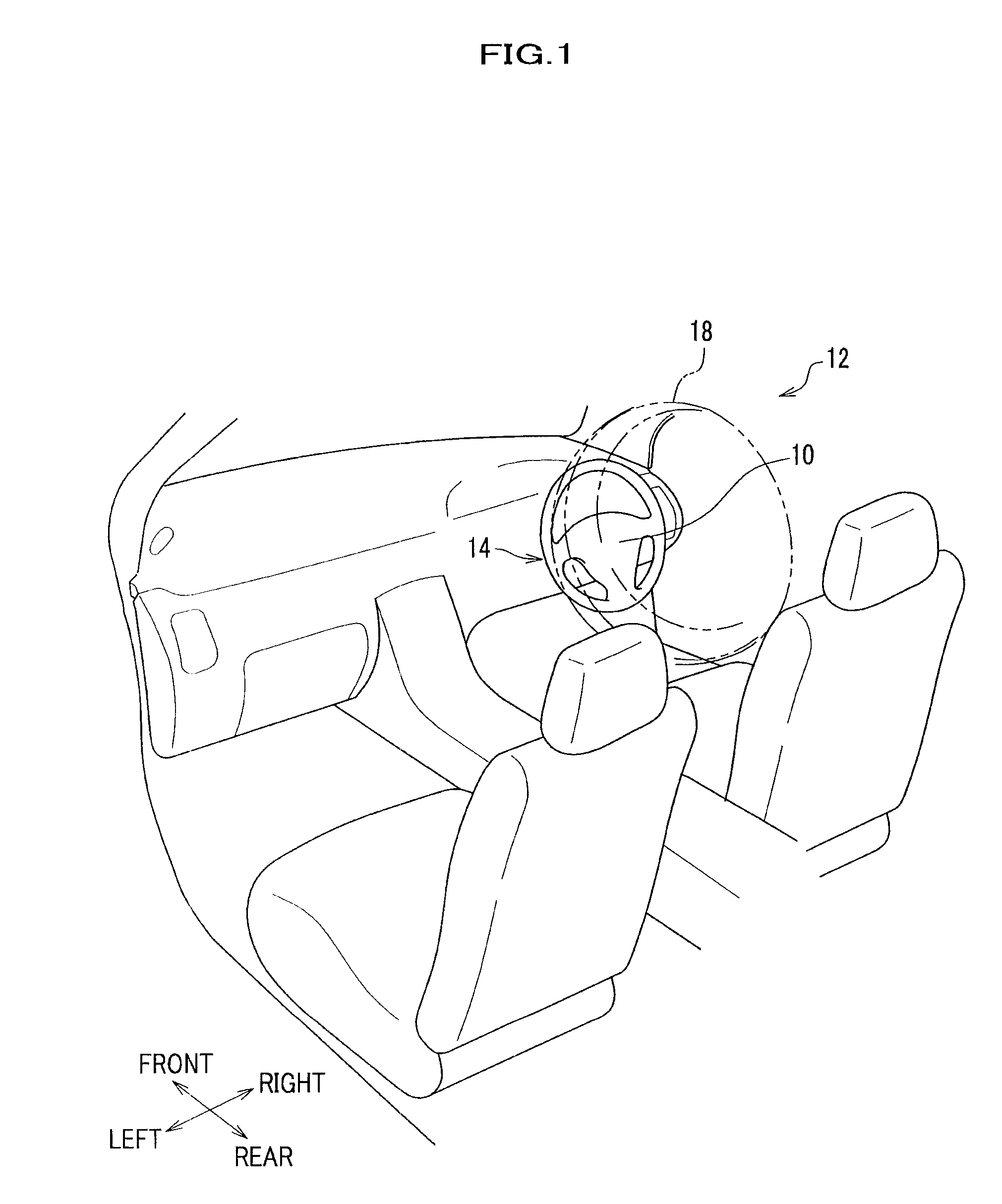
[0047]With reference to the drawings when necessary, descriptions are provided on the embodiment of the present invention hereinafter. FIG. 1 is a partially enlarged perspective view of a vehicle applied with an air bag system according to the embodiment of the present invention, and FIG. 2 is an exploded perspective view of the air bag system of FIG. 1.

[0048]The air bag system (air bag system for a vehicle) 10 according to the embodiment of the present invention is housed inside the steering wheel 14 installed in front of the driving seat. The air bag system 10 expands between the steering wheel 14 and a driver (not shown) to hold and protect the driver when collision energy is applied to the vehicle 12. The embodiment described hereinafter exemplifies the air bag system 10 housed inside the steering wheel 14, but the present invention is not limited to this, and may employ an air bag system of various types such as the air bag system housed inside an instrument panel at a driving ...


PUM


Abstract

An air bag system for a vehicle including an air bag in a folded state and installed in a vehicle. The air bag is inflated and expanded by gas from an inflator, which introduces gas into the air bag. A vent hole is formed in at least one base fabric piece of the air bag so as to establish a communication path between an inside and an outside of the air bag through which gas may be discharged from the inside toward the outside of the air bag. A blocking member is supported on the base fabric piece to block up the vent hole. A guide portion is provided to slidably support the blocking member and to restrict the position of the blocking member relative to the vent hole. A sliding resistance increasing portion is provided on at least either one of the guide portion and the blocking member, so as to increase a sliding resistance between the guide portion and the blocking member when the blocking member slides.

Description

CROSS-REFERENCE TO RELATED APPLICATION[0001]This application claims the foreign priority benefit under 35 U.S.C. §119 of Japanese Patent Application No. 2009-088851 filed on Apr. 1, 2009, the disclosure of which is incorporated herein by reference.BACKGROUND OF THE INVENTION[0002]1. Field of the Invention[0003]The present invention relates to an air bag system for a vehicle in which there is provided a vent hole in one of base fabric pieces that is a part of an air bag, so that gas flows from the vent hole toward the exterior of the air bag during the expansion of the air bag.[0004]2. Description of the Related Art[0005]There has been known an air bag that inflates and expands by gas supply from an inflator at the time of a collision of a vehicle, thereby to protect an occupant. Such an air bag is provided with a vent hole for discharging gas at an excessive pressure to the exterior of the air bag so as to prevent an excessive rise of gas pressure in the air bag.[0006]If such a vent...

Claims


Application Information

Patent Timeline
Patent Type & Authority Patents(United States)
IPC IPC(8): B60R21/239B60R21/203B60R21/16B60R21/26B60R21/2338B60R21/2334B60R21/231
CPCB60R21/239B60R21/2342B60R2021/2395
Inventor CHIDA, YUSUKENAGAI, MAKOTONOZAKI, HIROYUKI
Owner HONDA MOTOR CO LTD
Learn More