Lower structure of automotive vehicle

a technology for automotive vehicles and lower structures, applied in the field of lower structures of automotive vehicles, can solve the problems of improperly low support rigidity of suspension cross members, bolts that cannot be moved immediately, and suspension cross members that cannot be moved smoothly, etc., and achieve the effect of reducing collision load

Active Publication Date: 2012-09-18
MAZDA MOTOR CORP
View PDF12 Cites 29 Cited by
  • Summary
  • Abstract
  • Description
  • Claims
  • Application Information

AI Technical Summary

Benefits of technology

[0013]An object of the present invention is to provide a lower structure of an automotive vehicle which can secure the support rigidity of the suspension cross member during the normal vehicle traveling and achieve the smooth retreat of the power unit to restrain the collision load from having bad influence on passengers in the vehicle frontal collision.

Problems solved by technology

Thus, there is a concern that the support rigidity of the suspension cross member would be improperly low.
Further, since the bolt is fixed firmly to the vehicle body in the normal state, the bolt may not be moved right away when the vehicle collision occurs.
Accordingly, there is a problem in that the suspension cross member could not be moved smoothly.
Thus, there is also a problem in that the suspension cross member could not be detached smoothly.
According to the structure disclosed in the above-described third patent document, meanwhile, there is no concept that it can be prevented by releasing the connection between the suspension cross member and the vehicle body that the smooth retreat of the power unit is hindered.
Further, this structure may not sufficiently increase the collision-energy absorption which is conducted at the vehicle front portion.
Accordingly, it would be impossible to properly restrain the collision load from having bad influence on passengers.
However, this gap may cause a decrease of the rigidity of the part of the vehicle near the connection portion during the normal vehicle traveling, so that there is a concern that the support rigidity of the suspension cross member would be improperly low.
In this case, the rigidity of a vehicle part near this bolt connection portion may be improperly low, so that there is a concern that the support rigidity of the suspension cross member would be decreased.
Further, since the connection between the middle support member and the connection member is released by the moving bolt itself, this releasing may not be conducted right away after the occurrence of the vehicle collision for the reason described above in the structures disclosed in the first and second patent documents.
Thus, there is also a problem in that the suspension cross member could not be detached smoothly.

Method used


Image

  • Lower structure of automotive vehicle
  • Lower structure of automotive vehicle
  • Lower structure of automotive vehicle

Examples


embodiment 1

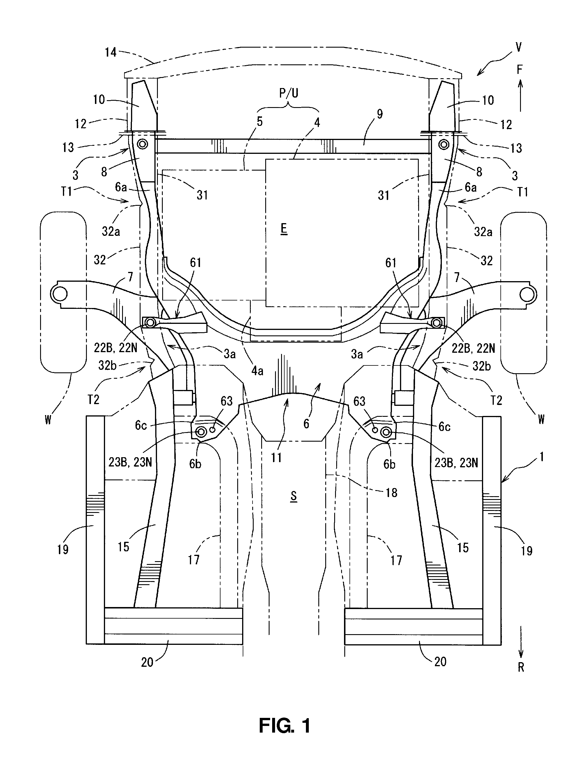
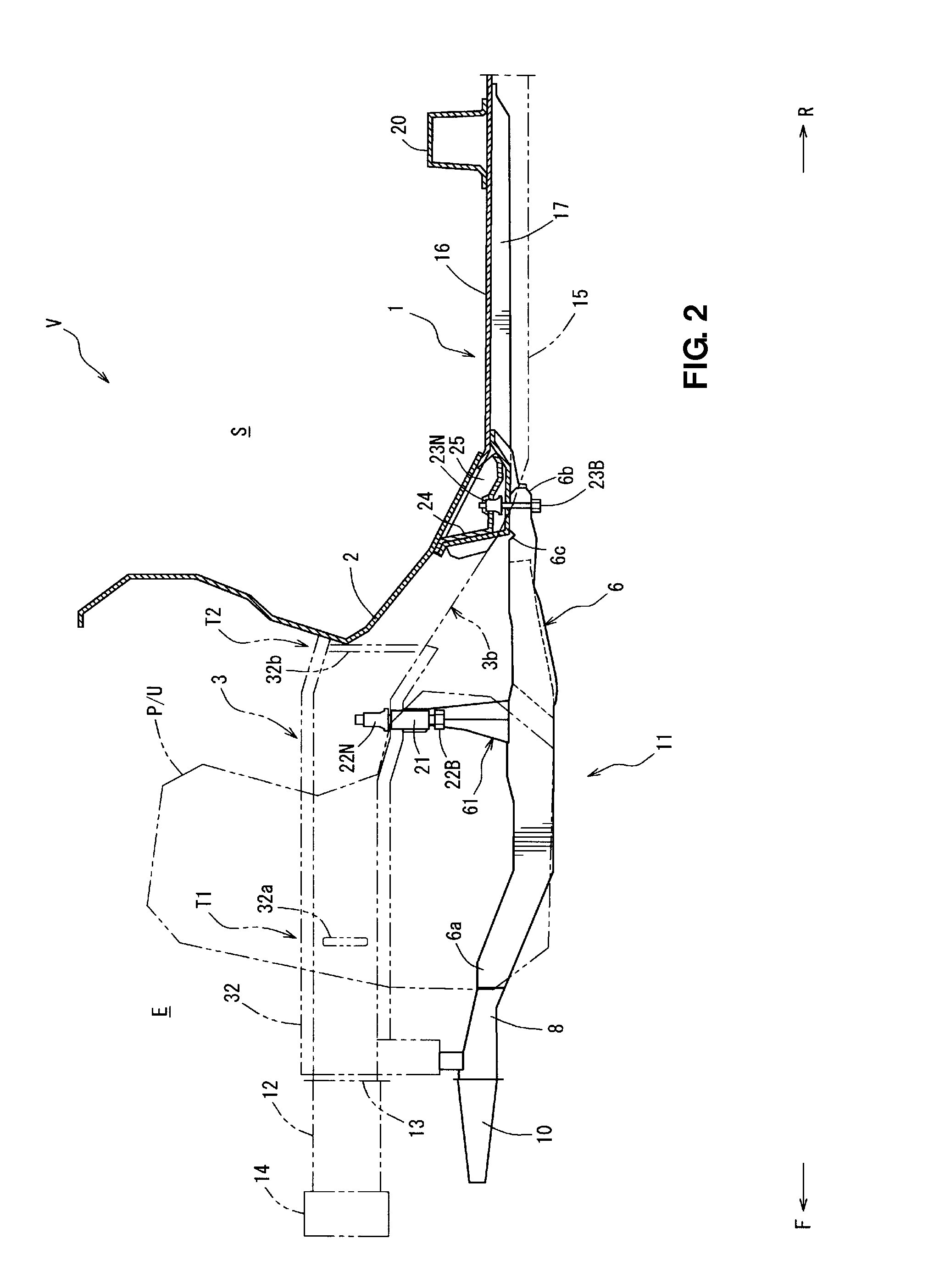
[0044]FIG. 1 is a plan view showing a lower structure of an automotive vehicle according to a first embodiment of the present invention, and FIG. 2 is a side sectional view showing the lower structure of an automotive vehicle. As shown in FIGS. 1 and 2, a vehicle body 1 of a vehicle V comprises a dash panel 2 (see FIG. 2) which partitions an engine room E from a vehicle room S and a pair of front side frames 3 which is provided in front of the dash panel 2. An arrow F shows a vehicle forward direction and an arrow R shows a vehicle rearward direction in the figures.

[0045]Between the pair of front side frames 3 is provided the engine room E, where a power unit P / U which comprises an engine 4, a transmission 5 and so on is arranged. Reference numeral 4a in FIG. 1 denotes an exhaust system of the engine 4. Herein, the present invention should not be limited to the vehicle equipped with the power unit P / U comprising the engine 4, but is applicable to any vehicle which is equipped with a...

embodiment 2

[0143]While the portion supporting the lower portion 21c of the pipe-shaped attaching member 21 is constituted by another member different from the front panel member 61B or the rear panel member 61C in the above-described embodiment first embodiment, the present invention should not be limited to this. For example, as shown by a middle-portion attaching member 71 in FIGS. 18 and 19, a lower support portion 71h which corresponds to the lower support member 61D may be formed integrally with a rear panel 71C. FIG. 18 is a perspective view showing the middle-portion attaching member 71 according to a second embodiment of the present invention. FIG. 19 is a sectional view taken along line E-E of FIG. 18. The same elements of the second embodiment as those of the above-described first embodiment are denoted by the same reference numerals, descriptions of which are omitted.

[0144]The middle-portion attaching member 71 is a vertical member which is comprised of a front panel member 71B and ...


PUM


Abstract

A positioning pin and a bolt hole positioned near this pin are provided at a plate-shaped rear-portion attachment face portion of a suspension cross member. A positioning hole having the positioning pin inserted thereinto and a bolt hole positioned near this positioning hole are provided at a tunnel frame on the side of a vehicle. The rear-portion attachment face portion and the tunnel frame are fastened by a bolt inserting into the bolt holes together with a nut. Accordingly, the support rigidity of the suspension cross member during the normal vehicle traveling can be secured and the smooth retreat of the power unit to restrain the collision load from having bad influence on passengers in the vehicle frontal collision can be achieved.

Description

BACKGROUND OF THE INVENTION[0001]The present invention relates to a lower structure of an automotive vehicle which comprises a suspension cross member provided behind a power unit and extending in a vehicle width direction and a plate-shaped vehicle-body-side support portion supporting the suspension cross member.[0002]Many structures which can absorb the vehicle-collision energy at a vehicle front portion in order to restrain the collision load from having bad influence on passengers in the vehicle room in a vehicle frontal collision or the like have been proposed.[0003]For example, Japanese Patent Laid-Open Publication No. 2004-130827 discloses a structure in which a through hole is provided, in the vicinity of a bolt hole, at a lower wall portion of a suspension cross member attachment portion of a front side member (front frame). In this structure, when a load of specified value or more acts on a bolt in the vehicle frontal collision, this bolt moves, expanding the bolt hole, an...

Claims


Application Information

Patent Timeline
Patent Type & Authority Patents(United States)
IPC IPC(8): B62D21/00
CPCB62D21/155B62D21/11
Inventor TAKESHITA, HIROAKIOTANI, TAKAHIROFUKUSHIMA, MASANOBUKUSAMA, RYUICHIHONJI, HIROMASA
Owner MAZDA MOTOR CORP
Why Eureka
Try Eureka