Tube for transporting high-viscosity materials

a technology of high-viscosity materials and tubes, which is applied in the direction of conveyors, rigid pipes, flexible pipes, etc., can solve the problems of release or peeling of inner pipes, and achieve the effect of facilitating the handling of pipes during assembly and during laying, and reducing structural weigh

Active Publication Date: 2006-03-16
XPERION
View PDF17 Cites 31 Cited by
  • Summary
  • Abstract
  • Description
  • Claims
  • Application Information

AI Technical Summary

Benefits of technology

[0033] The inventive transport pipes, due to their low structural weight, are suitable for employment in mobile or stationary concrete pumps with concrete distribution booms or long transport distances which require a large number of transport pipes. The inventive transport pipes can, with the same weight, be constructed to be several times longer than the known transport pipes. The handling during the assembly and during laying of the pipes is thereby substantially facilitated.

Problems solved by technology

With the proposed measures it is accomplished that the concrete situated in the transport pipes, although it may be able to penetrate into the separation gap between the end faces of two transport pipes joined to each other, however exerts or exercises no sheer forces on the flow between the inner pipe and the ring sleeve, which could lead to a release or peeling away of the inner pipe.

Method used


Image

  • Tube for transporting high-viscosity materials
  • Tube for transporting high-viscosity materials
  • Tube for transporting high-viscosity materials

Examples


example 1

[0047] The production of the inventive transport pipe occurs according to a first example embodiment in the following process steps:

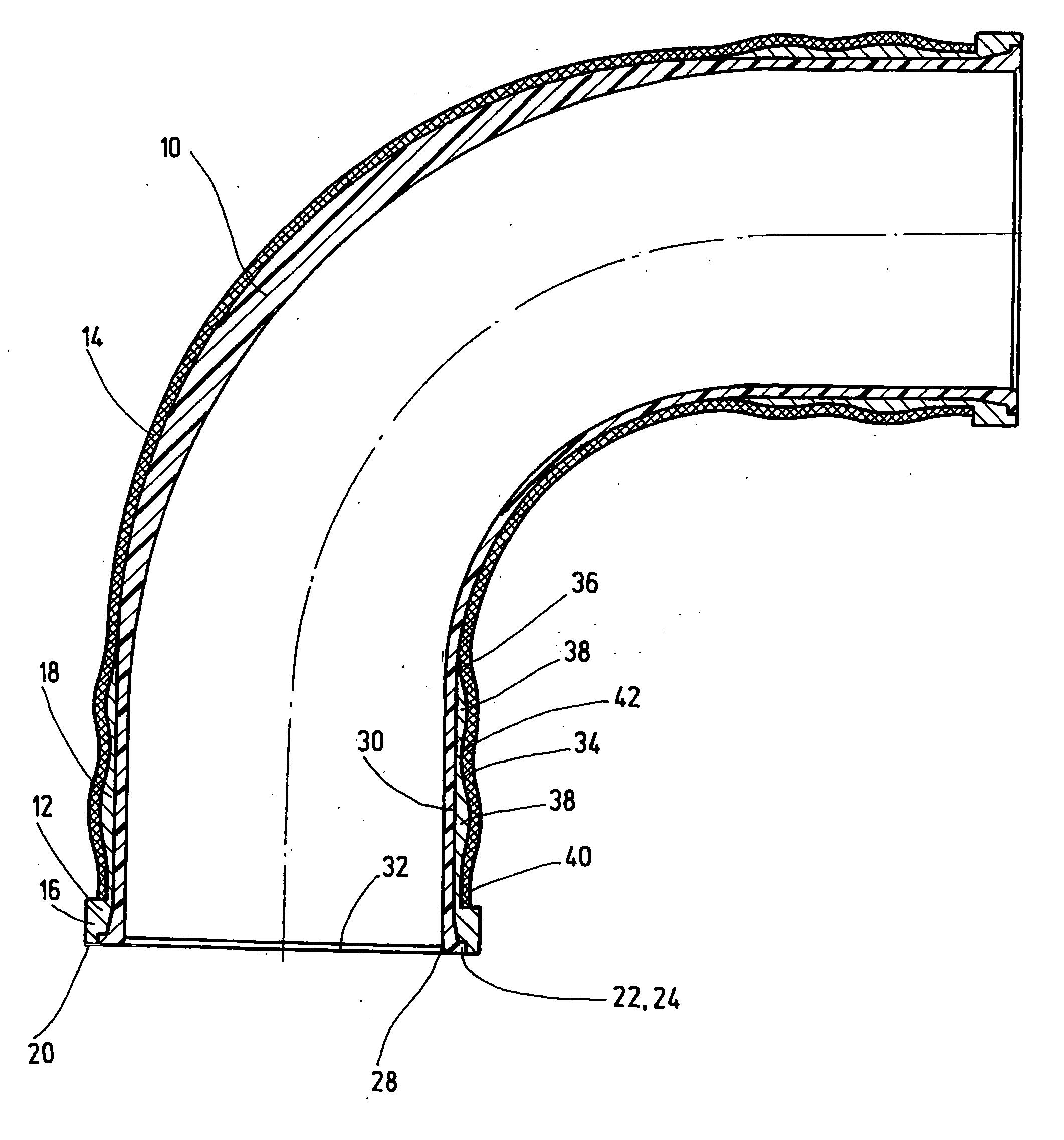
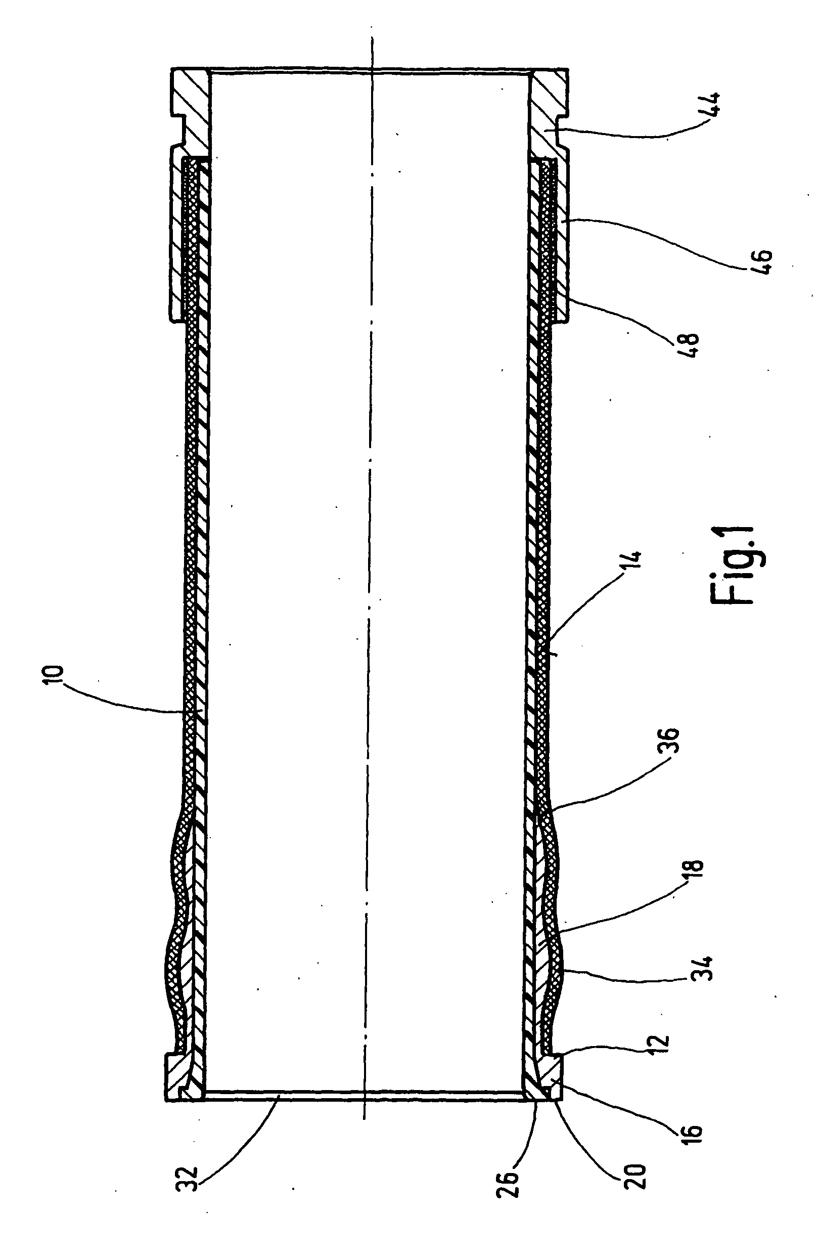
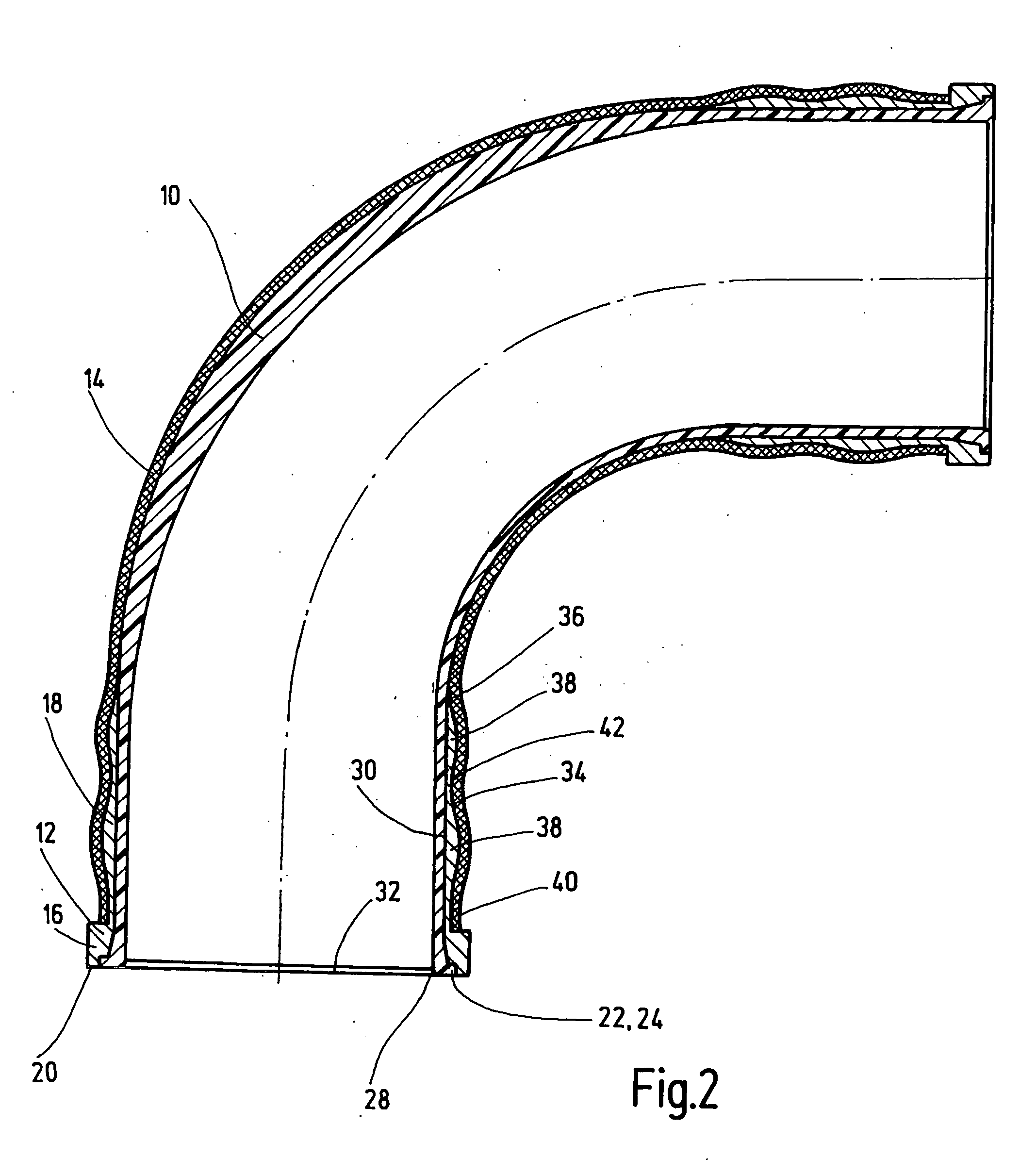
[0048] At least one premanufactured metallic joint part comprising a collar and an externally wave shaped ring sleeve is introduced on one end of a casting mold and there cast with a reaction plastic which is wear resistant in the cured state, with formation of an inner pipe with a collar or flange on one end;

[0049] The finished internal pipe with collar or flange is wound about with a plastic impregnated carbon fiber cord from one end to the other with the formation of the externally wave shaped ring liner and formation of a cohesive reinforcing jacket;

[0050] The finished transport pipe is heated for a period sufficient for curing the plastic matrix and / or for production of a form fitting joint with the inner pipe and the joint element.

[0051] In order to achieve also between joint element and inner pipe a reliable material engaging joint, the joint...

example 2

[0052] According to a second embodiment, the production of the transport pipe occurs with the following steps:

[0053] At least one premanufactured joint element comprising a collar and a ring sleeve, wave shaped on the outside, is wound with a plastic impregnated carbon fiber cord to form a carbon fiber composite pipe;

[0054] Then the produced carbon fiber composite pipe is cleansed on its inside, and the joint element is cleanses on its free contact surfaces and coated with an adhesion promoter;

[0055] Subsequently a reaction plastic is introduced into the carbon fiber composite pipe with its at least one collar, forming an inner coating, and there is cured.

[0056] Fundamentally, after coating the adhesion material, a core with smaller dimension or diameter can be introduced into the inside of the carbon fiber composite pipe provided with at least one collar, leaving free of a ring gap, wherein the reaction plastic is introduced into the ring gap and is cured there, and subsequentl...


PUM

PropertyMeasurementUnit
viscosityaaaaaaaaaa
inner radiusaaaaaaaaaa
wear resistantaaaaaaaaaa

Abstract

Transport pipe for high viscosity materials, in particular for concrete. The transport pipe includes an inner pipe (10) made of an abrasion-resistant plastic, at least one metallic joint element (12), as well as a reinforcing jacket (14) which envelops at least the internal pipe. In order to ensure a reliable and enduring joint between inner pipe and joint element, it is proposed in accordance with the invention, that the radially projecting collar of the joint element is defined by a ring-shaped end face (20) and by a thereto joined ring step (22) extending radially towards the inside of the pipe and recessed axially from the ring-shaped end face, and wherein the plastic material of the inner pipe (10) engages in the ring step (22) from the inside of the pipe.

Description

BACKGROUND OF THE INVENTION [0001] 1. Field of the Invention [0002] The invention concerns a pipe (tube) for transporting high-viscosity materials, in particular concrete. [0003] 2. Related Art of the Invention [0004] Mobile concrete pumps are frequently employed in the construction industry, wherein concrete is conveyed through transport pipes from a source location to an application location. The transport pipes are generally located on the mast arms of a distribution mast, wherein the movement of a terminal hose over a site to be concretized can be directed using remote control. Further, it is known to use stationary concrete pumps, in which transport pipes are laid along the ground from the source site to the site of application. Due to the abrasive characteristics of flowing liquid concrete, the transport pipe must be manufactured from an abrasion-resistant material. Conventionally steel pipes are used for this, of which inner surface has been hardened or coated with a abrasion...

Claims


Application Information

Patent Timeline
Patent Type & Authority Applications(United States)
IPC IPC(8): F16L9/00B65G53/32B65G53/52E04G21/04F16L9/147F16L57/06
CPCB65G53/32B65G53/523F16L57/06F16L9/147F16L23/024E04G21/04E04G21/0418B65G53/52F16L23/12F16L47/24
Inventor WOLFRAM, MARKUSKASTEN, KNUTMACKLE, RAIMUNDMULLER, DIETMARMAURER, THOMAS
Owner XPERION
Why Eureka
Try Eureka