Dual piston accumulator

a technology of accumulators and pistons, applied in the direction of mechanical equipment, fluid-pressure actuators, pipe elements, etc., can solve the problems of not meeting the requirements of the conventional design type of accumulators, and the conventional design type of accumulators, and achieve the effect of low structural weigh

Active Publication Date: 2014-06-10
HYDAC TECH GMBH
View PDF12 Cites 6 Cited by
  • Summary
  • Abstract
  • Description
  • Claims
  • Application Information

AI Technical Summary

Benefits of technology

[0005]An object of the present invention is to provide an improved dual piston accumulator that is compact and has extremely low structural weight.

Problems solved by technology

Dual piston accumulators of the conventional design type, as described, for example, in U.S. Pat. No. 6,202,753 B1 for use in deep water drilling operations, do not meet these requirements.

Method used


Image

  • Dual piston accumulator
  • Dual piston accumulator
  • Dual piston accumulator

Examples


Embodiment Construction

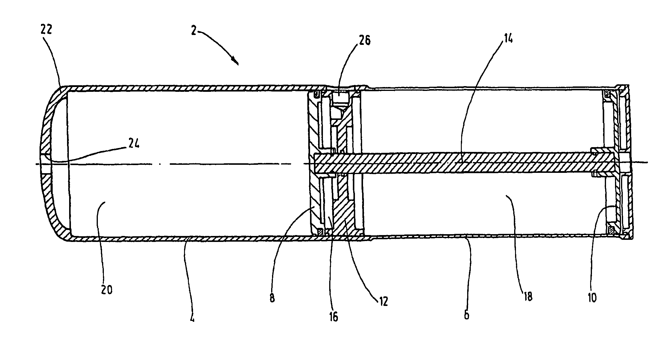
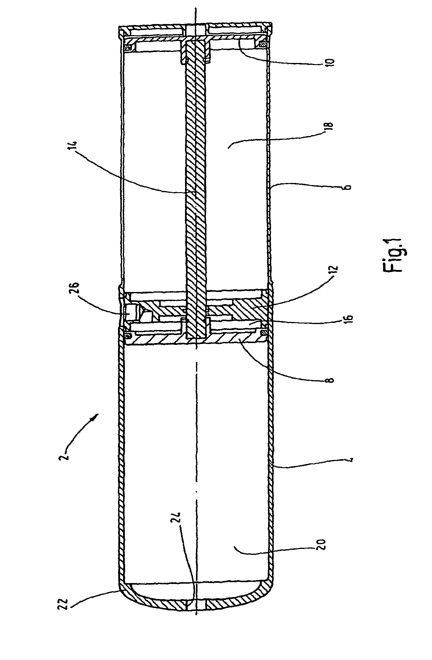
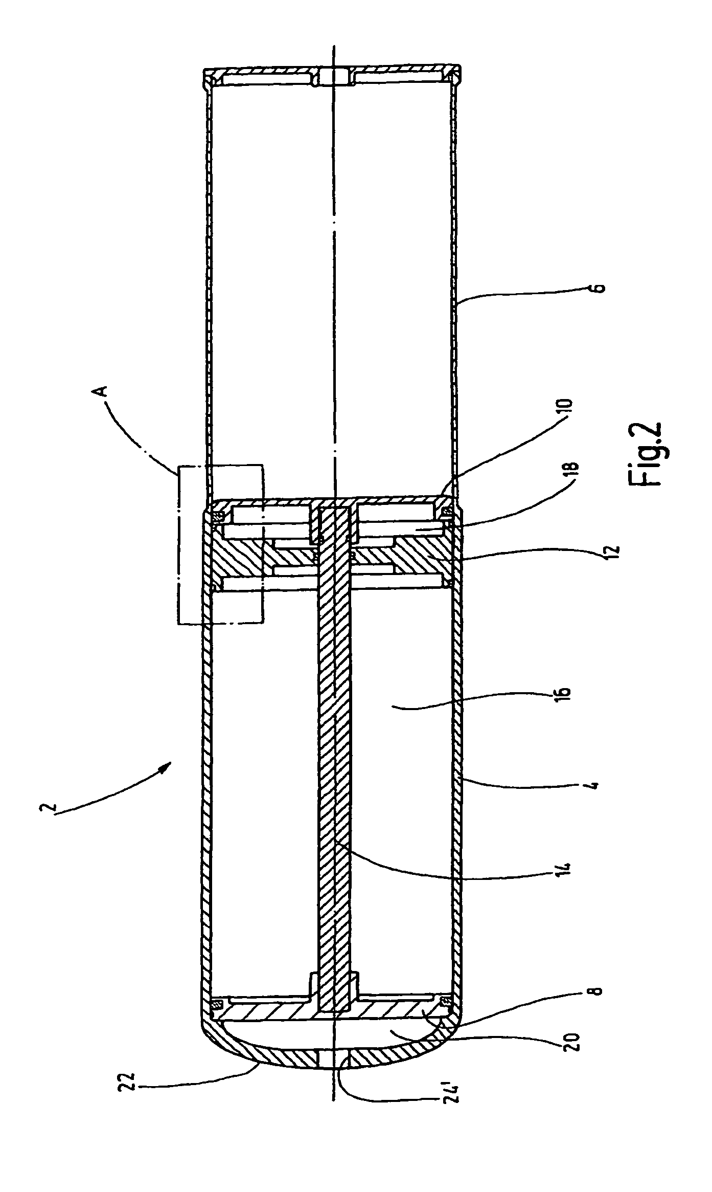
[0019]FIGS. 1 and 2 show a dual piston accumulator according to an exemplary embodiment of the invention with an accumulator housing 2. The accumulator housing 2 forms an inner cylinder designed in one piece extending continuously from a high pressure side 4 without a shoulder, that is, with a constant inside diameter, as far as to a low pressure side 6. In this case, a high pressure-side accumulator piston 8 and a low pressure-side accumulator piston 10 are guided such that they can be axially displaced in the inner cylinder. The high pressure side 4 and the low pressure side 6 are separated from each other in a fluid-tight manner by an intermediate piece 12 fixed in the inner cylinder. A piston rod 14 is connected to both accumulator pistons 8, 10 and extends in a fluid-tight manner through the intermediate piece 12. FIG. 1 shows the piston positions in which a high pressure-side fluid chamber 16 between the accumulator piston 8 and the intermediate piece 12 has its smallest volum...


PUM


Abstract

A dual piston accumulator, in particular for a hydrostatic hybrid drive system for vehicles, replaces a high pressure hydro accumulator and a low pressure hydro accumulator. Inside a single accumulator housing (2) extending in the axial direction in a single piece over a high pressure part (4) and a low pressure part (6), an accumulator piston (8, 10) defines a high pressure-sided fluid chamber (16) and a low pressure-sided fluid chamber (18). Both chambers border an intermediate piece (12) separating the high pressure side (4) from the low pressure side (6). A common piston rod (14) extends through the intermediate piece for both accumulator pistons (8, 10). The wall width of the housing (2) corresponding to the high pressure part (4) is greater than the opposite reduced wall width corresponding to the low pressure part (6).

Description

FIELD OF THE INVENTION[0001]The invention relates to a dual piston accumulator, which is provided, in particular, in a hydrostatic hybrid drive system for vehicles to replace a high pressure hydraulic accumulator and a low pressure hydraulic accumulator.BACKGROUND OF THE INVENTION[0002]In light of the scarcity of natural resources and the increasing impact of CO2 on the environment, the current trend in automotive engineering is to use hybrid drive systems, which store the electric energy generated in braking modes and recover drive energy from the stored energy to provide assistance to the vehicle for the drive mode and, in particular, for accelerating processes. This strategy offers the possibility of decreasing the drive power of the internal combustion engine, which serves as the primary drive, for comparable road performance. The result of such “downsizing” is not only a reduction in the fuel consumption, but it also raises the possibility of assigning the vehicles concerned to...

Claims


Application Information

Patent Timeline
Patent Type & Authority Patents(United States)
IPC IPC(8): F16L55/04
CPCF15B1/24F15B1/04F15B2201/405F15B2201/31
Inventor DORR, WALTERBALTES, HERBERTKLOFT, PETER
Owner HYDAC TECH GMBH
Why Eureka
Try Eureka