Composition having PTFE as main component, mixed powder, material for molding, filtering medium for filter, air filter unit, and a method for manufacturing a porous membrane

a technology of filter media and porous membrane, which is applied in the direction of filament/thread forming, synthetic resin layered products, textiles and paper, etc., can solve the problems of fold filtering medium, high pressure loss, and increase in the price of filtering medium, and achieve low filling ratio, high air permeability, and low pressure loss

Active Publication Date: 2015-03-26
DAIKIN IND LTD
View PDF13 Cites 29 Cited by
  • Summary
  • Abstract
  • Description
  • Claims
  • Application Information

AI Technical Summary

Benefits of technology

[0025]When a porous membrane is produced by using the composition or the like of the present invention, for example, the obtained porous membrane is unlikely to have deformation caused by external force even when the filling ratio of a molded article is low. For such reasons, when the produced porous membrane has low filling ratio but high air permeability, not only a filtering medium with a low pressure loss can be obtained by using it, but as the low density structure is maintained, the filter life span is also significantly improved so that the life span like a glass fiber filter can be achieved. Further, as the

Problems solved by technology

However, there is a problem that it has a high pressure loss.
However, there is a problem that, since a pressure loss easily increases due to an occurrence of surface filtration as caused by a dense structure of the porous PTFE membrane, the life span is equal to or less than half of a glass fiber filter.
However, because the filtering medium thickness increases according to adhesion of MB non-woven fabric, and thus there is a problem that an area to which

Method used


Image

  • Composition having PTFE as main component, mixed powder, material for molding, filtering medium for filter, air filter unit, and a method for manufacturing a porous membrane
  • Composition having PTFE as main component, mixed powder, material for molding, filtering medium for filter, air filter unit, and a method for manufacturing a porous membrane
  • Composition having PTFE as main component, mixed powder, material for molding, filtering medium for filter, air filter unit, and a method for manufacturing a porous membrane

Examples


first embodiment

[0035]Hereinbelow, the composition, mixed powder, material for molding (these three may be also collectively referred to as a composition or the like), porous membrane, filtering medium for a filter, air filter unit, and method for manufacturing a porous membrane according to the first embodiment are described. The composition or the like is described in conjunction with the description of method for manufacturing a porous membrane.

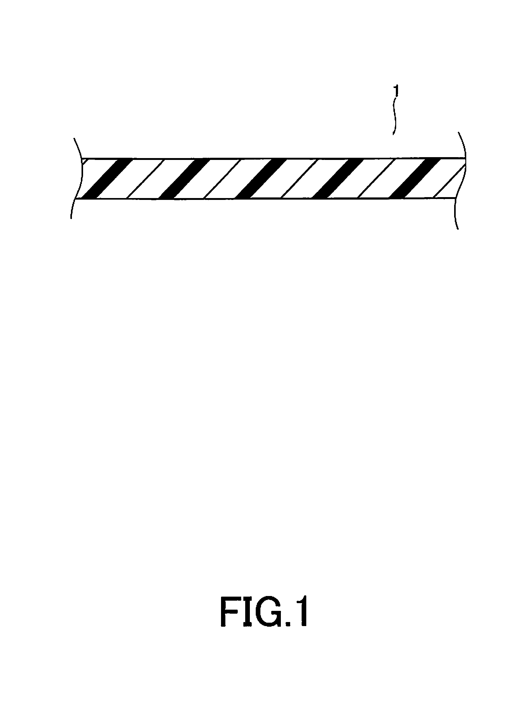
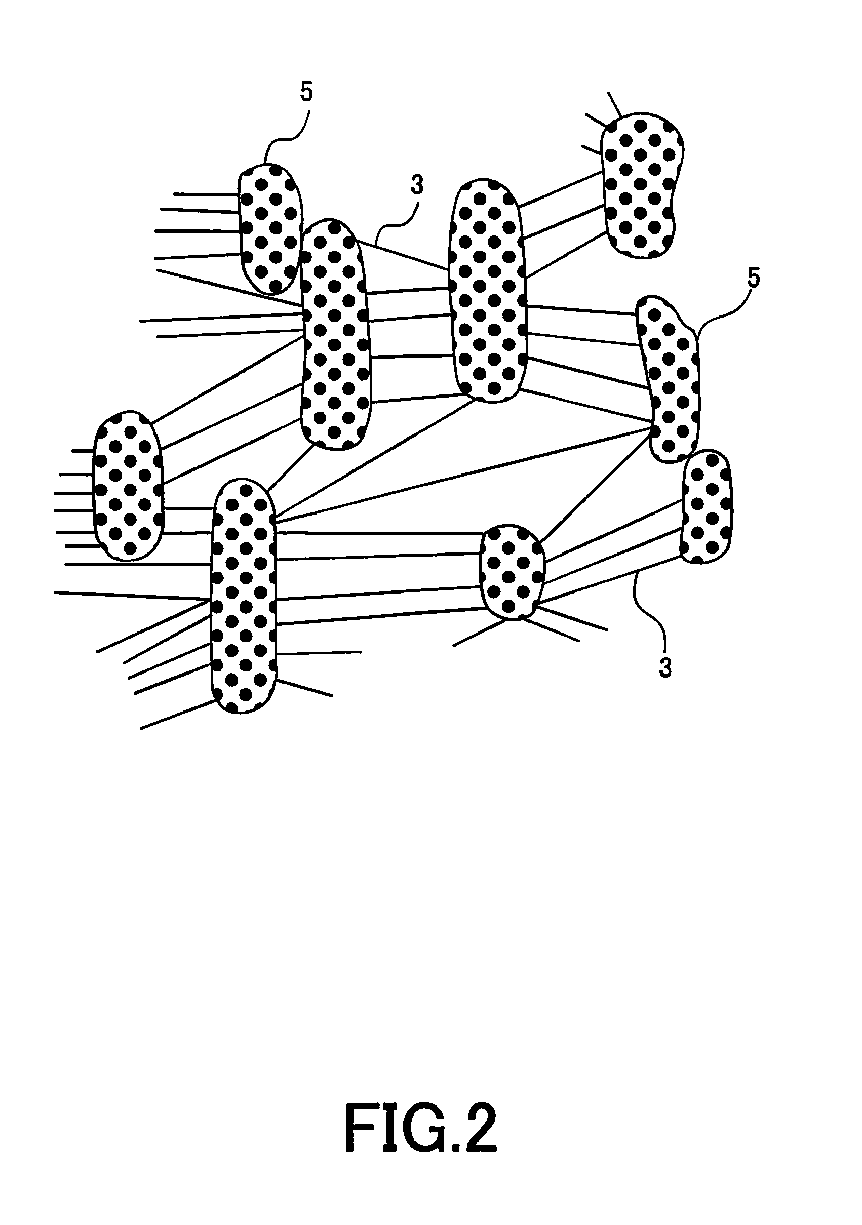
[0036]FIG. 1 is a schematic drawing illustrating the porous membrane. FIG. 2 is a drawing describing the structure of the porous membrane. The porous membrane 1 is used for a filtering medium to capture dust in fluid, and it has the fibril 3 and the knotted portion 5 that is connected to each other via the fibril 3.

(Fibril)

[0037](a) Polytetrafluoroethylene that can be Fibrillated

[0038]The fibril 3 includes polytetrafluoroethylene that can be fibrillated. The polytetrafluoroethylene that can be fibrillated is high molecular weight PTFE which is obtained by...

second embodiment

[0133]Hereinbelow, the method for manufacturing a filtering medium for an air filter, air filter unit, and porous membrane according to the second embodiment is described.

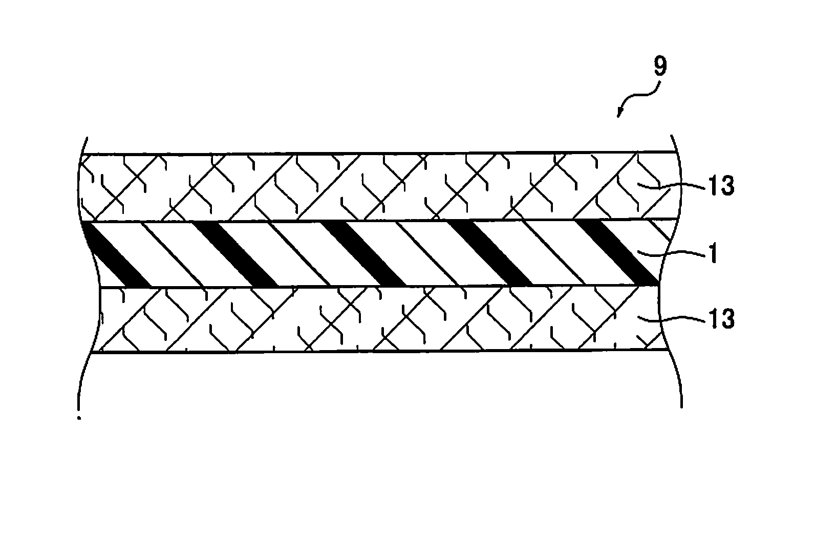
[0134]FIG. 3 is a drawing illustrating the cross section of the filtering medium 9 for an air filter of this embodiment in thickness-direction. FIG. 5 is a drawing illustrating the cross section of the filtering medium 10 for an air filter of this embodiment in thickness-direction. FIG. 5 illustrates the filtering medium with a five layer structure.

[0135]The filtering medium 10 for an air filter is a filtering medium for an air filter which includes one or more porous membrane 1 having PTFE as a main component and a plurality of air permeable supports 13 which supports the porous membrane 1 and is arranged at least on the outermost layer, in which the pressure loss when air is passed through at a flow rate of 5.3 cm / sec is less than 200 Pa, the PF value represented by the following equation is 17 or higher when air...

example 1

[0198]66.5% by weight (in terms of polymer) of PTFE aqueous dispersion (PTFE-A) with SSG of 2.160, which was prepared based on the method described in Comparative Example 3 of WO 2005 / 061567 A, 28.5% by weight (in terms of polymer) of low molecular weight PTFE aqueous dispersion (PTFE-B) with melt viscosity of 20000 Pa·s measured by a flow tester method at 380° C., which was prepared based on the method described in WO 2009 / 020187 A, and 5% by weight (in terms of polymer) of FEP aqueous dispersion having melting temperature of 215° C., which was prepared based on the method described in JP 2010-235667 A, were admixed with one another. After adding 500 ml of 1% aqueous solution of aluminum nitrate as a coagulating agent followed by stirring, co-coagulation was performed. After removing the moisture from the produced powder by using a sieve, it was dried again for 18 hours in a heat wave furnace at 135° C. to obtain mixed powder with the aforementioned three components.

[0199]Subsequen...


PUM

PropertyMeasurementUnit
Temperatureaaaaaaaaaa
Lengthaaaaaaaaaa
Lengthaaaaaaaaaa

Abstract

A composition, a mixed power and a material for molding have polytetrafluoroethylene as a main component. Each includes polytetrafluoroethylene that can be fibrillated, a non-hot melt processable component that is not fibrillated, and a hot melt processable component with a melting point of lower than 320° C. that is not fibrillated. The hot melt processable component is contained at equal to or more than 0.1% by weight but less than 20% by weight of a total weight. A filtering medium for an air filter includes a porous membrane made of these components, and an air permeable support. The porous membrane is manufactured, by mixing these components, extruding the mixture, rolling and drawing.

Description

TECHNICAL FIELD[0001]The present invention relates to a composition having PTFE as a main component, mixed powder, a material for molding, a filtering medium for filter, an air filter unit, and a method for manufacturing a porous membrane.BACKGROUND ART[0002]Manufacturing a semiconductor device or a liquid crystal display device is performed in a highly clean space. To create a highly clean space, a porous membrane composed of polytetrafluoroethylene (PTFE) (hereinbelow, also referred to as a “porous PTFE membrane”) is used as a filter for collecting fine particles. From the viewpoint of having high efficiency for collecting fine particles compared to a filtering medium composed of glass fiber with the same pressure loss, the porous PTFE membrane is particularly preferably used for a HEPA filter (High Efficiency Particulate Air Filter) or a ULPA filter (Ultra low Penetration Air Filter).[0003]As a HEPA filter, a filtering medium composed of glass fiber has been conventionally used. ...

Claims


Application Information

Patent Timeline
IPC IPC(8): B01D46/54B29D99/00B29D7/01B01D46/00C08L27/18
CPCB01D46/543B01D46/0019B01D46/0001C08L27/18C08L2205/025B29D99/005B29K2027/18B29K2105/0005C08L2205/03B29D7/01B01D67/0002B01D71/36B32B27/322C08K3/36C08L83/04B01D46/56
Inventor CHAEN, SHINICHIKIYOTANI, HIDEYUKIINUI, KUNIHIKOYAMANAKA, TAKUBAO, LISHIBUYA, YOSHIYUKIYAMAMOTO, SEIGOKOBAYASHI, MAKOTOKASAI, SHUNJINIINUMA, HITOSHI
Owner DAIKIN IND LTD
Why Eureka
Try Eureka